


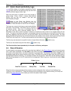
Section 3 – Installation
Page 23 09/11/2008 REV 0.99
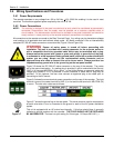
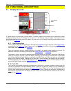
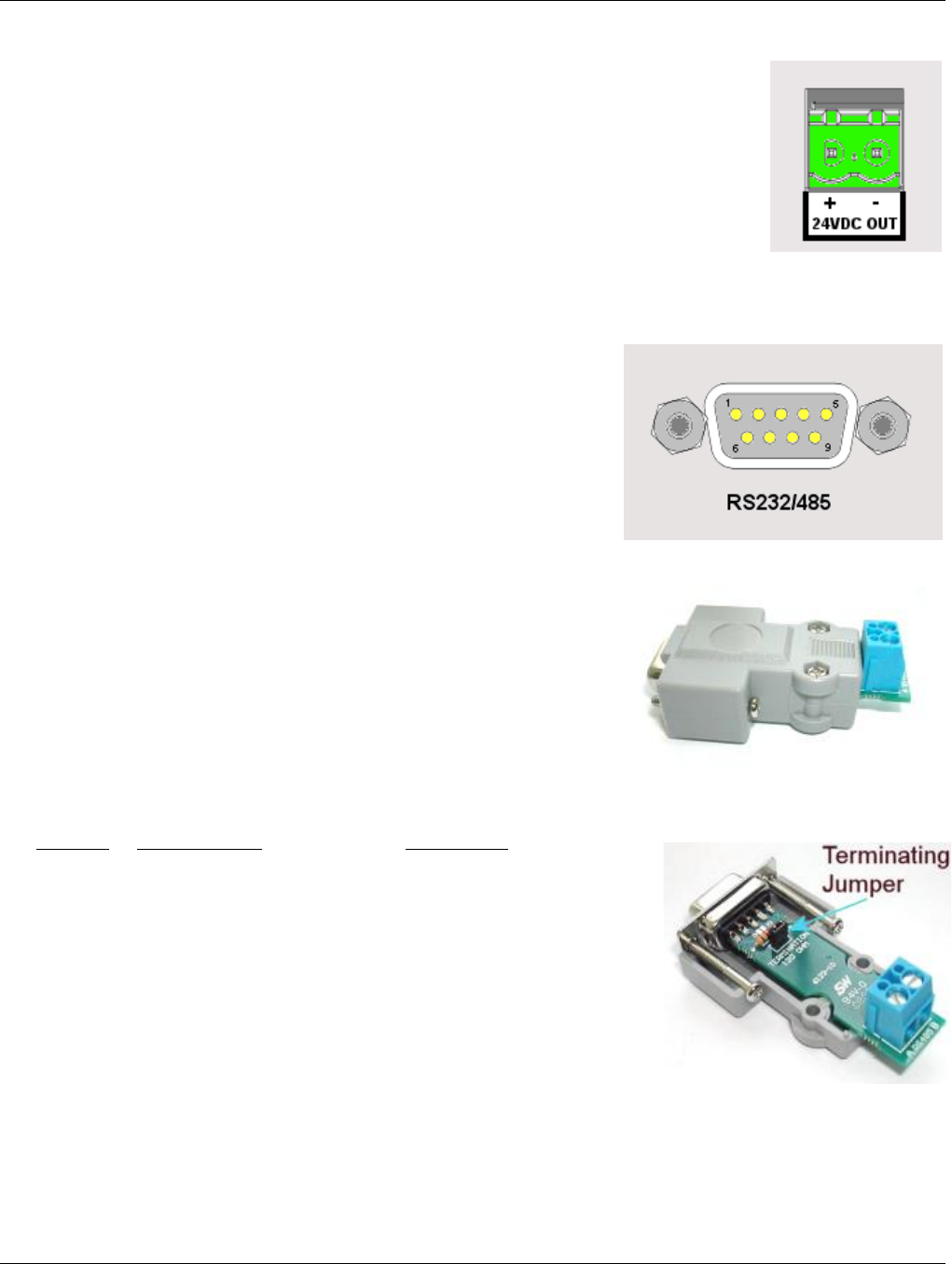
3.9 24Vdc Isolated Output (Option)
The Isolated 24Vdc Output is an option that provides 24 Volts DC @ 100 milliamps to
power external (current loop) sensors. The output is isolated to 1000 volts from all internal
voltages and ground. The output is also protected against short circuit.
The output is polarized and is marked for positive (+) and negative (-). This option is field
installable.
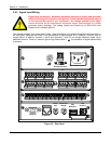
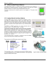
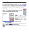
3.10 Isolated Serial Interface (Option)
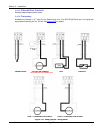
A standard DB9 Female connector is required for the RS232 to connect
to an IBM PC compatible computer using a null modem cable. The
RS232 interface can support cable runs up to 50 feet [16 m]. The RS485
connection is via two wire (twisted pair) cable (a DB9 Female adapter
connector is required) and can support cable runs up to 4000 feet [1300
m].
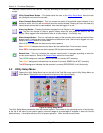
The RS232 and RS485 connections are mutually exclusive and are
selected using pin 1 of the DB9 connector – see right.
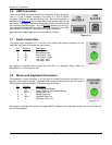
The interface is isolated from internal circuitry to 500 volts. The RS485
requires a 120 ohm terminating resistor if it is the last unit on the drop. All
Serial Interface connections are made through the DB9 female
connector. An adapter connector is included that brings out the RS485
connections to a set of screw terminals and has the terminating resistor on
the board. The RS485 connection is marked A and B for duplex 2 wire
connection. A is + and B is -.
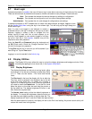
If the terminating resistor is required it is necessary to open the adapter
shell and insert the jumper to enable the termination.
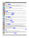
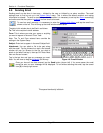
The connections to the DB9 female connector are as follows:
DB9 PIN CONNECTION DIRECTION
1 Mode Select (see below) In
2 RxD Receive Data In
3 TxD Transmit Data Out
4 DTR Data Terminal Ready Out
5 Common Out
7 RTS Request To Send Out
8 CTS Clear to Send In
6 RS485 A+ Bidirectional
9 RS485 B- Bidirectional
The mode select pin (pin 1) must be left unconnected for RS232 operation
or must be grounded (to pin 5) for RS485 communication. Use the provided
adapter for RS485 communication
Figure 3-16
Figure 3-17 Serial I/O
Fig 3-18 RS485 Adapter
Fig 3-19 RS485 120 Ohm Jumper