


Section 3 – Installation
Page 17 09/11/2008 REV 0.99
3.4 Wiring Specifications and Procedures
3.4.1 Power Requirements
The recorder operates on any voltage from 100 to 240 Vac +10%, 50/60 Hz enabling it to be used in most
countries. The maximum apparent power required by the unit is 35 VA.
3.4.2 Power Connections
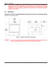
NOTE: The recorder is designed to be panel mounted and as such should be considered as permanently
connected. Disconnection from the supply must be possible via a customer supplied switch or
circuit breaker. This disconnection device must be included in the panel installation and should be
clearly marked, in close proximity to the recorder and easily accessible to the operator.
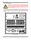
All connections to the recorder are made to the Rear Terminal Panel. Any wiring carrying hazardous voltages
must conform to all applicable local and national safety codes. AC Mains connection is via an internationally
accepted IEC 320 AC mains connector or screw terminal (Figure 3-5 and Figure 3-6).
WARNING Ensure all mains power is turned off before proceeding with
installation. This unit is provided with a mating connector for the ac power socket or
with a compatible three wire grounded cable which may be terminated with a plug.
Always ensure the ground wire (green or green and yellow) or ground pin of the plug,
is connected to a low impedance safety ground (earth) within the ac power distribution
system you are using. Always use the recommended mating connector and an
approved three wire cable to connect this unit to the ac mains. Always provide a low
impedance safety ground wire to the ground lug on the rear panel marked.
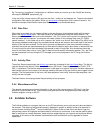
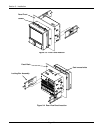
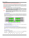
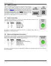
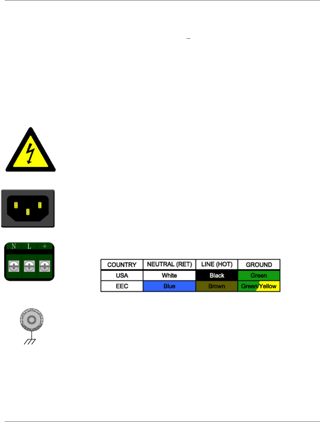
Figure 3-5 shows the IEC 320 AC mains connector on the rear of the recorder. The center
pin is the ground termination. If a mating plug is provided, it will be marked with the Ground,
LINE (L) or hot, and NEUTRAL (N) or return. In the United States, an approved cable with
integral plug (NEMA 5-15 P) is provided. In some instances, a cable with no plug may be
provided. In this instance, the user must connect an approved plug to the cable prior to
connecting to the AC source.
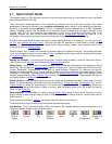
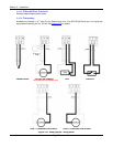
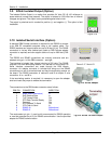
Figure 3-6 shows the screw terminal power connections on the rear of the recorder. The right
terminal is ground, the center terminal is LINE (L) or hot and the left terminal is NEUTRAL (N)
or return. The wire color codes are as follows:
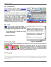
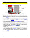
Figure 3-7 shows the ground lug on the rear panel. This screw terminal must be connected to
an earth wire which in turn is connected to the ground or earth of the AC power distribution
system.
This unit is equipped with an AC mains fuse internally. If this fuse should blow, it generally
indicates a serious problem with the recorder. THE FUSE SHOULD NOT BE REPLACED
BY AN OPERATOR. The fuse is a quick acting 5 x 20mm type - 2.0 Amps 250 VAC (~).
Figure 3-5
Figure 3-6
Figure 3-7