


Section 2 - Overview
Page 7 09/11/2008 REV 0.99
have an isolated frequency inputs which allows the unit to measure frequency to 10,000 Hz. Between the
terminal blocks is the ambient temperature sensor for thermocouple compensation.
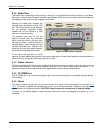
2.4.3 Input/Output Module
The input/output module is optional and provides potential free relay contacts and isolated digital inputs.
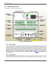
2.4.4 Computer Interface
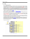
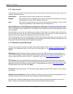
The bottom of the rear panel is the computer interface. At the bottom right hand corner is a small cover
secured by a screw. This is the internal memory expansion slot – it takes standard secure digital memory
cards.
Above this are the two USB ports – the type A port (to the left) is a master port and the type B port is a slave
port. These are mutually exclusive ports and the user needs to select which port will be active. This is done by
using the small slide switch on the underside of the unit – indicated but not shown in Figure 2-4 above. Slide
the switch toward whichever connector is being used. The Type of port selected, A or B depends on what is to
be connected to it.
To the left of these connectors are two mini-din style connectors. The mouse / keyboard connector allows the
use of an external PS2 PC style mouse directly or a PS2 PC style keyboard using an available adapter board
which will accommodate both mouse and keyboard together. The audio connector is to the left and allows the
audio output from the unit to be fed to an external amplifier.
The Ethernet connector is the standard RJ45 type and allows a 100 Mbps (megabits per second) connection
to be made to the network. There are two indicator LEDs, the one on the right shows connection speed either
10 Mbps unlit or 100 Mbps when lit. The led on the left is the activity led and it blinks when the link is active
and data is being transmitted.
On the left is the optional RS232/RS485 legacy connector. This is a factory installed option. Normally there is
a blanking panel over the opening.