


Section 3 – Installation
Page 19 09/11/2008 REV 0.99
Read the following procedures prior to connecting inputs to the terminals.
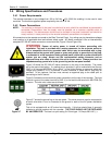
WARNING: Ensure the power is off before connecting signal inputs to the unit.
The plug in screw terminal connectors are of the clamping screw variety, putting even pressure on the signal
wire. It is therefore not necessary to terminate the wires with lugs, however you may do so if you wish. The
maximum gauge wire that can be accommodated is 14 AWG or 2.5 mm². You will need a small screwdriver
and a pair of wire cutters and strippers. The use of shielded twisted lead wire is recommended to minimize
electromagnetically induced noise.
WARNING: All unused inputs must have + and - contacts commoned together.
CAUTION: Never run signal and power or control wiring together in the same conduit. This is to
prevent possible recording error due to induced signals between lines. If running cables
is inevitable, use shielded cable where possible and properly ground the shield. Route
signal wires away from power wires at the rear panel.
NOTE: Ground cable shields at one end only to eliminate the possibility of interference due to
ground loop currents. When grounded transducers are used, the shield should be
grounded at the sensor end only.
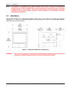
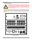
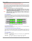
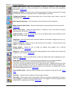
3.4.3.1 Analog Inputs
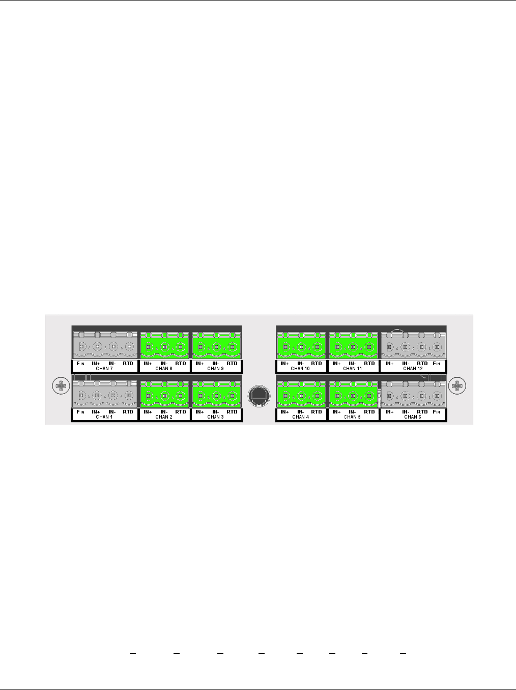
The Analog Input board can have 6 or 12 channels (12 shown below). Each Input is truly differential and
has a positive (IN+) and negative (IN-) input and an RTD Common (COM) for RTD current return and
Frequency input Common ONLY. Channels 1 and 6 (and optionally 7 and 12) have a Frequency Input
(FIN) which is common with the COMmon input. All inputs are isolated to 350 Vac from each other and
2,000 Vac from the chassis ground.
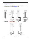
3.4.3.2 Thermocouple Inputs
Thermocouple Input connections are made as shown in Figure 3-10 T/Cs. The ambient temperature
compensator is between inputs 3 and 4.
3.4.3.3 Resistance Temperature Detector (RTD) Inputs
Two or three wire RTDs may be used for connection with cable compensation of up to ±50 ohms. The
“COM” Terminal is the common current return (Wire 3). Four wire RTDs can be used – simply do not
connect the second + wire. Two wire RTDs require a jumper between (IN-) and (COM). Refer to Figure
3-10
3.4.3.4 Linear Inputs
Linear Inputs are divided into two types:
Current inputs: 4-20 milliamps, 0-20 milliamps and 10-50 milliamps, using an external 50 ohm
shunt (0.1% 0.5W).
Voltage inputs: +125mV, +250mV, +500mV +1.00V, +3.0V, +6.0V, +12.0V, +24.0V DC.
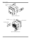
Figure 3-9 Analog Input Module (12 Channels shown)