


Section 5 – Recorder Setup
Page 40 09/11/2008 REV 0.99
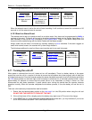
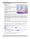
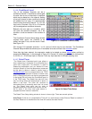
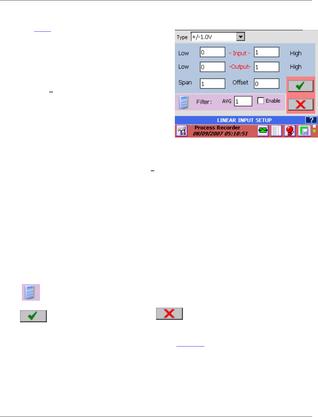
Figure 5-3 Linear Input Setup
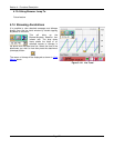
5.1.3 Channel Type Setup
The Channel Type Setup dialog window is dependent upon the type of input selected in the Channel Setup
window above.
5.1.3.1 Linear Input
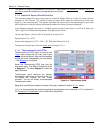
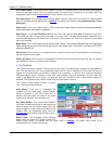
For Linear Voltage and Current the dialog box is
shown in right. For other input types it will differ.
Select the Type from the pull down item list. The
following ranges are available.
Voltage: + 125mV, 250mV, 500mV, 1V, 3V, 6V, 12V
and 24V full scale.
Current: 4-20mA, 0-20mA and 10-50mA. NOTE :
When selecting currents it is necessary to provide a
terminating resistor of 50 ohms at 0.1% across the
terminal inputs.
Dry Contacts: This option is for use with potential
free contacts - used for logic inputs. Display will show OPEN or CLOSED accordingly.
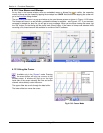
Input/Output Ranges: Figure 5-3 shows the +1.0 Volt input range for the analog input. The Input and
Output ranges LOW and HIGH values set the scaling for the channel. They default to the zero and high
values for the range so that the channel reads the full scale range. As shown when the input is zero the
output will read zero, and when the input is 1 volt the output will read 1. If the Output - HIGH was set to
100 then the output would be 0 to 100 for an input of 0 to 1V. The input is effectively multiplied by the
(Output High)/(Input High).
Span: The span is a correction value that is multiplied by the full scale input and applied linearly across
the range. The default is 1.
Offset: The offset is an adder (subtractor) that is added or subtracted to the output. Thus in the equation
y = ax + b, y is the final output, x is the input value, a is the span multiplier and b is the offset. The default
is 0.
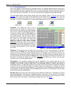
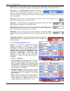
Filter: The filter is applied to the inputs when the Enable check box is checked. The filter performs a
running average of n samples, where n is the numeric value set in the AVG box from 1 to 100.
Calculator: This will bring up a simple calculator that allows the user to do computations to
calculate the scaling factors if needed.
Apply: Save the values and exit
Cancel: Exit without making any changes.
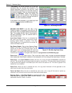
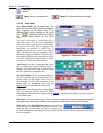
5.1.3.2 Resistance Input
The Resistance setup dialog window is similar to that in Figure 5-3 above. Resistance measurement uses
a constant current source through the load, measures the voltage and computes:
Resistance = Current x Voltage.
There are three resistance ranges which are selected via the pull down menu.
Resistance Ranges: 100 ohm, 500 ohm and 5000 ohm