


C1572M (9/05) 99
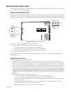
CM9760-DFC REAR PANEL DOWNFRAME CARD
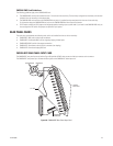
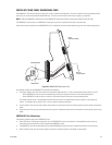
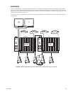
The CM9760-DFC rear panel card (refer to Figure 53) is used in a downframe configuration. The card is installed in every bay between the first
and last bay to connect the associated intermediate bays. The card can also be used in the last bay if looping is not required.
NOTE: Unlike the CM9760-DFL downframe card, the CM9760-DFC downframe card does not provide the ability to loop out video.
The CM9760-DFC card connects to a CM9760-VCC video input card, which is installed into the front of the matrix bay.
A downframe cable is supplied with the CM9760-DFC card. For additional information about downframing, refer to the Downframing section.
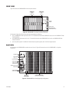
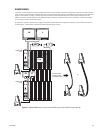
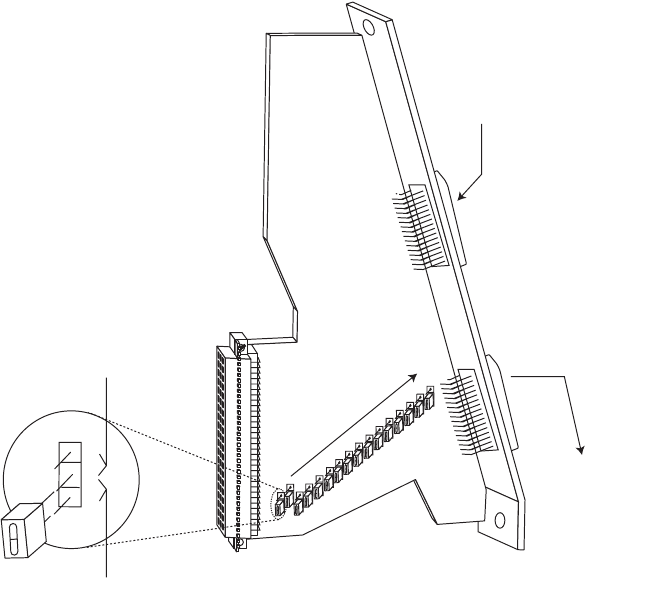
Figure 53. CM9760-DFC Downframe Card
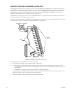
As illustrated in Figure 53, the CM9760-DFC card includes the following:
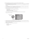
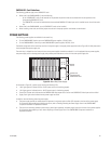
• Termination Jumpers JP1-JP16: Allow video to be terminated (jumper positions 1 and 2) or unterminated (jumper positions 2 and 3):
– When CM9760-DFC cards are used in intermediate bays, termination jumpers must be set in the unterminated position.
– When CM9760-DFC cards are used in the last bay, termination jumpers must be set in the terminated position.
Termination jumpers are set in the appropriate position when your system is configured at the factory. However, if you change your
system—for example, add or replace a card—you may need to change the termination.
• Input Connector: Thirty-two pin male connector that connects to a downframe cable, which then connects to the rear panel card in the bay
above.
• Output Connector: Thirty-two pin male connector that connects to a downframe cable, which then connects to the rear panel card in the bay
below.
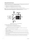
CM9760-DFC Card Guidelines
The following guidelines apply to the CM9760-DFC card:
• Within each bay in a downframe configuration, up to 16 CM9760-DFC cards can be inserted into 16 possible slot positions that are
associated with the slot positions of the corresponding CM9760-VCC cards.
• The CM9760-DFC must be installed before the associated CM9760-VCC video input card is installed into the front of the matrix bay.
• When installing a new card, termination jumpers must be set in the proper position: terminated or unterminated.
JP
1
JP
16
UNTERMINATED
TERMINATED
3
2
1
OUTPUT
TO BAY BELOW
INPUT
FROM BAY ABOVE