


72 C1572M (9/05)
System Diagnostics
The 9760 system provides diagnostic screens that allow you to monitor single-node and multi-node status. This section provides information
about the following:
• Monitoring CM9700-CC1 functions using the CM9700-CC1 diagnostic screen and associated PC keyboard commands
• Viewing multi-node system status using the CM9700-NW1 diagnostic screen and associated PC keyboard commands
NOTE: Additional displays, such as those provided by the CM9700-MGR Main window and the CM9760-KBD LCD, also provide information
about system status. For detailed information, refer to the product-specific documentation.
MONITORING CM9700-CC1 FUNCTIONS
The CM9700-CC1 provides a diagnostic screen that allows you to monitor CM9700-CC1 functions. You can view the diagnostic screen on a VGA
monitor that is connected to the VGA port on the rear of the CM9700-CC1. The diagnostic screen appears after the CM9700-CC1 initializes.
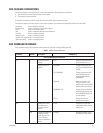
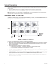
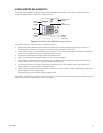
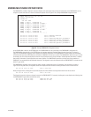
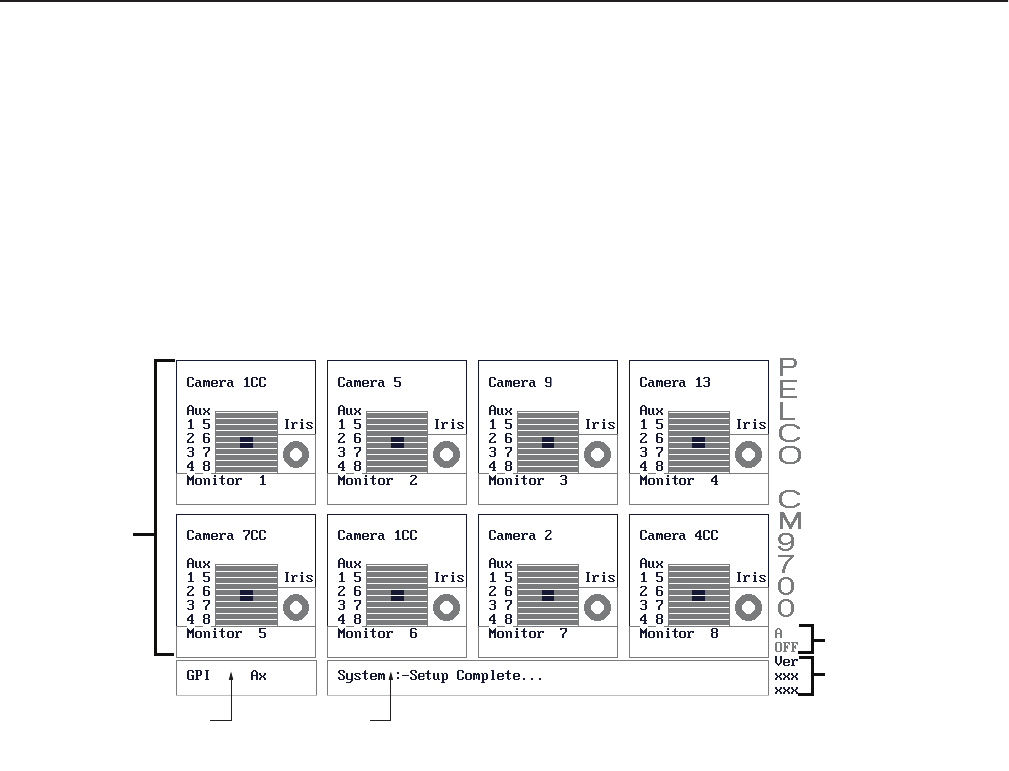
Refer to Figure 35 for a sample CM9700-CC1 diagnostic screen.
Figure 35. Sample CM9700-CC1 Diagnostic Screen
As illustrated in Figure 35, the CM9700-CC1 diagnostic screen displays the following items:
• Monitor boxes: Up to eight monitor boxes are displayed on the CM9700-CC1 diagnostic screen at one time. Each monitor box represents a
monitor and the camera currently being displayed on that monitor (for detailed information about the monitor box, refer to the Viewing
Monitor Box Diagnostics section).
• GPI and auxiliary box: Displays GPI and auxiliary information (if applicable):
– GPI displays the GPI currently selected. The GPI number is updated when an auxiliary command is executed.
– Ax displays the auxiliary currently selected and whether the auxiliary is on or off.
• System box: Displays system status messages, error messages, and responses to commands issued from the PC keyboard that is connected
to the AT-compatible port of the CM9700-CC1.
• Configuration information: Indicates whether the CM9700-CC1 is part of a CM9760-HS hot switch configuration. Note that A OFF indicates
that the CM9700-CC1 is not part of a hot switch configuration. (The letter A indicates asynchronous mode.) For detailed information about
the diagnostic screen in a hot switch configuration, refer to the CM9760-HS Hot Switch Installation/Operation manual.
• CM9700-CC1 software version: Displays the software version number (xxx xxx) of the CM9700.EXE executable file (for example, version
903 023 which represents version 9.03.023).
MONITOR
BOXES (8)
GPI AND
AUXILIARY
BOX
SYSTEM
BOX
CONFIGURATION
INFORMATION
CM9700-CC1
SOFTWARE
VERSION