


104 C1572M (9/05)
Note the following:
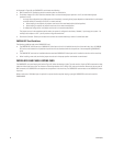
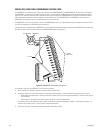
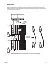
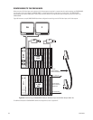
• In an initial system installation, multiple matrix bays are labeled to identify the location of the sideframed bays in the installation, for
example, 2A, 12A, 22A, and so on. Figure 56 illustrates a two-bay configuration in which bay 12A (output bay) is sideframed to bay 2A
(bay 1). For additional examples of sideframe configurations, refer to Appendix B.
• Video outputs of a bay connect to the video inputs in the output bay by means of BNC coaxial cables. Each coaxial cable connection from
one bay sideframed to the output bay is referred to as a tie line. Alternatively, as shown in Figure 56, a coaxial ribbon cable can be used in
a two-bay sideframed configuration to connect the 16-pin connector on the bottom of the CM9760-RPM card to the 16-pin connector on the
bottom of the CM9760-RPC card.
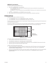
• Any video input connector not used in the output bay to receive output from sideframed bays can be used for additional video inputs.
• If you add one or more matrix bays to an existing installation by sideframing, you can avoid the need to reprogram the existing bay(s) by
adhering to the following guidelines:
– If you add one matrix bay, install and configure the new bay as the output bay.
– If you add more than one matrix bay, install and configure the last bay as the output bay.
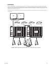
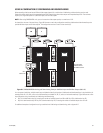
For example, to add a second matrix bay to an existing installation that contains only one bay, do the following. Decouple the monitors
connected to the video output card in the existing bay. If possible, leave the cables connected to the output card. Connect the cables to the
first 16 video inputs of the new bay. Connect the monitors to the video outputs of the new bay. The new bay then becomes the output bay.
If you wish to add a third bay to an existing two-bay installation, decouple the monitors of the existing output bay (second bay). If possible,
leave the cables connected to the output card. Connect the cables to the second 16 video inputs of the new bay. The new bay then becomes
the output bay (third bay). Then, detach the monitor output cables of the original bay from the first 16 inputs of the second bay and connect
them to the first 16 inputs of the new bay.