


C1572M (9/05) 45
INSTALLING OR REPLACING A CM9760-VCC VIDEO INPUT CARD
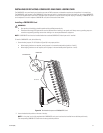
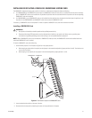
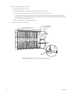
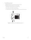
CM9760-VCC video input cards are installed into the front of the matrix bay behind the front panel. For an initial system installation, the cards
are installed at the factory as ordered. CM9760-VCC cards (and associated rear panel cards) can be added to expand a system or can be replaced
if necessary. To install or replace a CM9760-VCC card, refer to the sections that follow.
INSTALLING A CM9760-VCC CARD
Before installing a CM9760-VCC card, note the following:
• A CM9760-VCC card can be installed while the matrix bay is powered on.
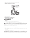
• A CM9760-VCC card can be installed into any available slot ranging from slot 1 to slot 16, totaling a maximum of 16 CM9760-VCC cards.
A CM9760-VCC card cannot be installed into slot 17—slot 17 is reserved for the CM9760-VMC video output card.
• Each slot position (slots 1-16) into which a CM9760-VCC card can be installed corresponds to a specific range of physical inputs; for
example, slot position 1 corresponds to physical inputs 1-16, slot position 2 corresponds to physical inputs 17-32, and so on. Physical input
numbers are used when programming the CM9760-MXB using the CM9700-MGR; therefore, if you do not install CM9760-VCC cards in
sequential order, be sure to use the correct physical input numbers when programming the CM9760-MXB.
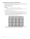
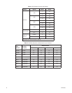
Table F lists the 16 slot positions and their corresponding physical input range.
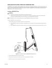
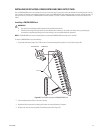
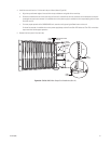
• The CM9760-VCC card requires a rear panel input card: CM9760-RPC, CM9760-RPL, CM9760-DFC, or CM9760-DFL. The associated rear
panel input card should be installed into the correct slot in the rear of the matrix bay before a CM9760-VCC card is installed.
For instructions to install rear panels cards, refer to the Installing or Replacing Rear Panel Cards section.
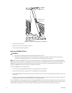
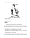
WARNINGS:
• CM9760-VCC video input card installation should be performed by qualified personnel only.
• Electrostatic discharge (ESD) precautions must be observed when installing a CM9760-VCC card. Always wear a grounding strap
connected to an approved grounding source when working on or near exposed electronic equipment.
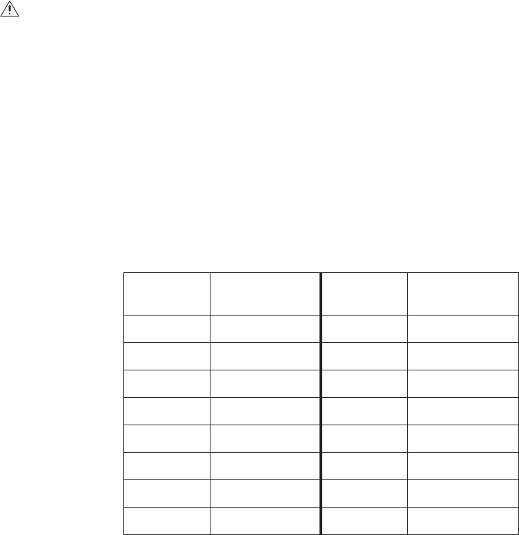
Table F. CM9760-VCC Slot Positions and Corresponding Physical Input Range
Slot
Position
Physical
Input Range
Slot
Position
Physical
Input Range
1 1-16 9 129-144
2 17-32 10 145-160
3 33-48 11 161-176
4 49-64 12 177-192
5 65-80 13 193-208
6 81-96 14 209-224
7 97-112 15 225-240
8 113-128 16 241-256