


52 C1572M (9/05)
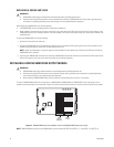
REPLACING A CM9760-VMC CARD
Before replacing a CM9760-VMC card, note the following:
• The CM9760-RPM card can be replaced while the matrix bay is powered on.
• When installed in the matrix bay at the factory according to your system order, the S2 DIP switch and X55 and JP2 jumper settings on the
CM9760-RPM card are set in the proper position. You must, however, set DIP switch and jumper settings on a new card as instructed in the
procedure below.
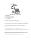
To replace the CM9760-VMC card, do the following:
1. Remove the front panel of the matrix bay.
2. Remove the CM9760-VMC card to be replaced by grasping the two card handles and firmly pulling the card out of the connectors on the
backplane and associated rear panel card. The card slides out of the slot.
3. Install the new CM9760-VMC card (refer to the Installing a CM9760-VMC Card section). Note that you should set the S2 DIP switch and the
X55 and JP2 jumpers on the new card to match the settings on the card being replaced.
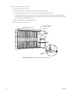
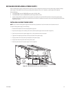
INSTALLING A CM9760-VMM VIDEO OUTPUT MODULE
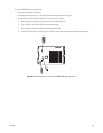
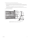
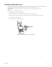
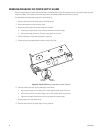
To install a CM9760-VMM module into an empty slot on a CM9760-VMC4, CM9760-VMC8, or CM9760-VMC12 card, align the pins on the
module with the three sockets on the card (refer to Figure 31) and push the card down carefully until the pins are firmly seated into the sockets.
Figure 31. CM9760-VMM Video Output Module Locations (CM9760-VMC8 Video Output Card)
NOTE: CM9760-VMM slot locations on the CM9760-VMC card are numbered OUTPUT 0 to OUTPUT 15—not OUTPUT 1 to OUTPUT 16.
WARNINGS:
• CM9760-VMC video output card replacement should be performed by qualified personnel only.
• Electrostatic discharge (ESD) precautions must be observed when replacing a CM9760-VMC card. Always wear a grounding strap
connected to an approved grounding source when working on or near exposed electronic equipment.
NOTE: Unless the audible alarm on the power supply has been disabled, the alarm beeps and the Frame Fault LED flashes red when the
CM9760-VMC card is removed.
WARNINGS:
• CM9760-VMM video output module installation should be performed by qualified personnel only.
• Electrostatic discharge (ESD) precautions must be observed. Always wear a grounding strap connected to an approved grounding
source when working on or near exposed electronic equipment.
• When installing a CM9760-VMM module, exercise caution to prevent bending any of the pins on the module.
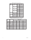
OUTPUT 0
OUTPUT 6
OUTPUT 5
OUTPUT 4
OUTPUT 3
OUTPUT 2
OUTPUT 1
OUTPUT 12
OUTPUT 11
OUTPUT 10
OUTPUT 9
OUTPUT 8
OUTPUT 7
OUTPUT 15
OUTPUT 14
OUTPUT 13
VIDEO
OUTPUT
MODULES
EMPTY
SLOTS