


C1572M (9/05) 19
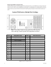
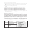
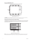
In the sample port assignment table shown in Figure 5, note the following:
• CM9700-CC1 port 1 (COM 1) is assigned and configured for the System Manager; therefore, the System Manager PC should be connected
to COM 1 on the CM9700-CC1.
• CM9700-CC1 port 2 (COM 2) is not assigned or configured for any device.
• Because CM9700-CC1 ports 3 and 4 are not present on the CM9700-CC1, ports 3 and 4 are grayed out and are described as NOT
AVAILABLE.
• CM9700-CC1 port 5 is assigned and configured for the CM9760-MXB labeled 2A containing video outputs 1-16; therefore, the
CM9760-MXB labeled 2A should be connected to port 5 on the CM9700-CC1.
• CM9700-CC1 port 6 is assigned and configured for the CM9760-MXB labeled 2B containing video outputs 17-32; therefore, the
CM9760-MXB labeled 2B should be connected to port 6 on the CM9700-CC1.
• CM9700-CC1 port 7 is assigned and configured for the CM9760-MXB labeled 2C containing video outputs 33-48; therefore, the
CM9760-MXB labeled 2C should be connected to port 7 on the CM9700-CC1.
• CM9700-CC1 port 8 is assigned and configured for the CM9760-KBD having a pin number of 1111; therefore, the CM9760-KBD should be
connected to port 8 on the CM9700-CC1.
• Because no additional devices are included in the system, CM9700-CC1 ports 9-36 are not assigned or configured for any device.
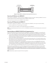
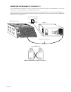
SERCOM Port Device Priority Connections
The CM9760-HS hot switch, CM9700-NW1 network interface unit (required in a networked system), and CM9760-MXB matrix bays must be
connected to SERCOM ports in a particular order based on device priority. The CM9760-HS has the highest priority and, if present in the system,
always connects to SERCOM port 5. The CM9700-NW1 has the next highest priority if present in the system, followed by CM9760-MXBs. If
neither a CM9760-HS nor a CM9700-NW1 is present, then CM9760-MXBs have the highest priority and must be connected to the CM9700-CC1
starting at port 5. As a result, the order of connections depends on whether the system includes a CM9760-HS hot switch, a CM9700-NW1, or
both. Note that CM9760-MXBs must be connected in sequential order. After all CM9760-MXBs have been connected, all other devices—such as
keyboards—can then be connected in any order.
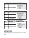
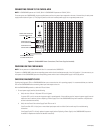
Table A, Table B, Table C, and Table D provide a list of the appropriate order of device connections to SERCOM ports in various types of systems.
The tables also include the device tree view portion of the CM9700-MGR Main window. The device tree identifies the appropriate port number
assigned to each device in the system.
NOTE: For all systems configured at the factory, COM 1 is always configured as the port to be used with the System Manager PC.
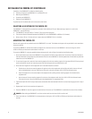
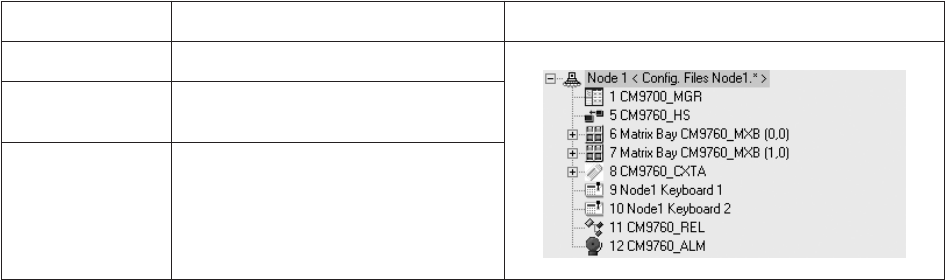
Table A. RS-422 SERCOM Port Connections in a Single-Node System with a CM9760-HS Hot Switch
Device SERCOM Port Connection CM9700-MGR Device Tree Port Assignments
CM9760-HS Port 5
CM9760-MXB(s) Port 6 and next sequential ports as necessary—
connected through the hot switch
Other devices Any available ports connected through the hot
switch—connections do not have to be in
sequential ports