


C1572M (9/05) 93
VIDEO INPUT AND OUTPUT CARDS
The CM9760-MXB accommodates up to 16 CM9760-VCC video input cards and one CM9760-VMC video output card. The cards are installed into
the front of the matrix bay (behind the front panel).
CM9760-VCC VIDEO INPUT CARD
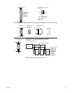
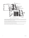
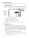
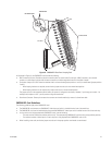
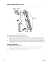
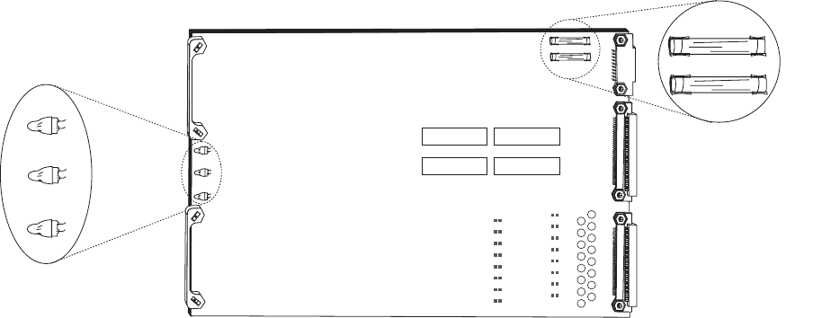
The CM9760-VCC video input card (refer to Figure 48) accepts up to 16 video input signals and performs the actual video switching in the bay. The
CM9760-VCC card can switch any one of 16 video input signals to any video output or to multiple combinations of video outputs up to 16. Video
input sources (for example, cameras) to the CM9760-VCC card are connected to the associated rear panel BNC card (CM9760-RPC or CM9760-RPL).
Figure 48. CM9760-VCC Video Input Card
As illustrated in Figure 48, the CM9760-VCC card includes the following:
• CR1, CR2, and CR3 LEDs: Allow you to monitor the operating status of the card:
– CR1: Lights red to indicate a communication failure with the CM9700-CC1.
– CR2: Lights green to indicate that the +10 VDC power source is functioning properly.
– CR3: Lights green to indicate that the –10 VDC power source is functioning properly.
• Power Fuses: Two .7ASB fuses (F1 and F2)
For troubleshooting information relating to the LEDs and fuses on the CM9760-VCC card, refer to Troubleshooting the CM9760-MXB in the
Troubleshooting section.
CM9760-VCC Card Guidelines
The following guidelines apply to the CM9760-VCC card:
• The CM9760-VCC card can be installed into any available slot ranging from slot 1 to slot 16 in the front of the matrix bay. Up to 16
CM9760-VCC cards can be installed in a single matrix bay. The matrix bay is shipped from the factory with the required number of cards
installed in the unit according to the system order. For information about installing additional CM9760-VCC cards or replacing an existing
card, refer to Installing or Replacing a CM9760-VCC Video Input Card in the CM9760-MXB Component Installation or Replacement section.
• Each slot position into which a CM9760-VCC can be installed (1-16) corresponds to a specific range of physical inputs; for example, slot
position 1 corresponds to physical inputs 1-16, slot position 2 corresponds to physical inputs 17-32, and so on. Physical input numbers are
used when programming the CM9760-MXB using the CM9760-MGR; therefore, if you do not install CM9760-VCC cards in sequential order,
be sure to use the correct physical input number when programming the system. Refer to Installing a CM9760-VCC Card in the CM9760-
MXB Component Installation or Replacement section for a complete list of CM9760-VCC slot positions and their corresponding physical
input range.
• The CM9760-VCC card can connect to various rear panel cards:
– In a non-looping single-bay configuration, the CM9760-VCC card connects to a CM9760-RPC card.
– In a single-bay configuration that requires looping, the CM9760-VCC card connects to a CM9760-RPL card.
– In a sideframed matrix bay, the CM9760-VCC card connects to a CM9760-RPC card. (For additional information about sideframing, refer
to the Sideframing section.)
– In a downframed matrix bay, the CM9760-VCC card connects to a CM9760-DFC card or to a CM9760-DFL card. (For additional
information about downframing, refer to the Downframing section).
For detailed information about rear panel cards, refer to the Rear Panel Cards section.
CR1
CR1
RED
RED
CR2
CR2
GREEN
GREEN
CR3
CR3
GREEN
GREEN
CR1 RED
CR2 GREEN
CR3 GREEN
F1
.7ASB
F2
.7ASB