


110 C1572M (9/05)
Appendix A. CM9700-CC1 ASCII Protocol Communication
The CM9700-CC1 provides support of ASCII communication. ASCII data ports, referred to as IDT ports on the CM9700-CC1, interface to ASCII
communication devices (ACDs) such as access control systems.
NOTE: When operating in ASCII mode, the KBD200A and KBD300A keyboards can interface to an IDT port of the CM9700-CC1.
When an ACD sends ASCII commands through a CM9700-CC1 IDT port, the CM9700-CC1 executes the commands. Up to 96 ACDs can be
connected to the CM9700-CC1 and be configured as IDT ports. IDT ports are configured using the CM9700-MGR.
NOTE: IDT ports eliminate the need for CM9760-DT/CM9760-DT4 devices, which are referred to as external DTs.
The ASCII protocol uses the ASCII character set to transmit and receive commands between an ACD and the CM9700-CC1. The commands are
used to control pan and tilt mechanisms (fixed and variable speed), camera functions, auxiliary relays, alarms, multiplexers, VCRs, and system
tasks such as macros.
An IDT port communicates in a standard asynchronous, byte-oriented protocol that includes 1 start bit; 8 data bits; odd, even, or no parity; and 1
stop bit.
This appendix provides information about the following:
• ACD to CM9700-CC1 connections
• ASCII protocol commands supported by the CM9700-CC1
ACD TO CM9700-CC1 CONNECTIONS
You can connect an ACD to the CM9700-CC1 in either of the following ways:
• ACD DB9 connection to CM9700-CC1 DB9 (COM 1 or COM 2) via RS-232 communication standard. Refer to the Connecting an ACD DB9
Port to a CM9700-CC1 DB9 Port section for wiring information.
• ACD DB9 (RS-232) connection to CM9700-CC1 RJ-45 (RS-422). In this case, the Pelco PV140 RS-232/RS-422 converter is used to provide a
bidirectional electrical interface between the RS-232 port of the ACD and the RS-422 port of the CM9700-CC1. Refer to the Connecting an
ACD DB9 Port to a CM9700-CC1 RJ-45 Port section for wiring information.
CONNECTING AN ACD DB9 PORT TO A CM9700-CC1 DB9 PORT
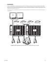
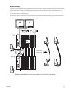
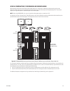
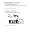
Connect a DB9 port of the ACD to the DB9 COM 1 or COM 2 port of the CM9700-CC1 using a null modem cable. Refer to Figure 60 for wiring
connections. In Figure 60, the ACD connects to the COM 2 port of the CM9700-CC1.
Figure 60. ACD DB9 to CM9700-CC1 DB9 Connection
COM1PRINTER COM2
5
6
7
8
10
9
11
12
19
18
17
16
15
14
1321
22
23
24
25
26
27
28
20
29
30
31
32
33
34
35
36
CM9700-CC1
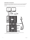
RS-232 NULL MODEM CABLE
NULL MODEM CABLE WIRING
ACD MALE
DB9 SERIAL
PORT
ACD
DB9 PORT
CM9760-CC1
DB9 PORT
PIN 2 = RX
PIN 3 = TX
PIN 5 = GND
PIN 2 = RX
PIN3 = TX
PIN 5 = GND