


84 C1572M (9/05)
REAR VIEW
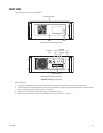
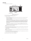
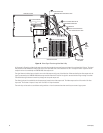
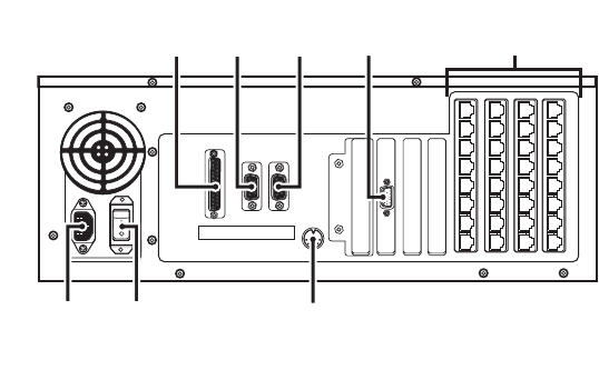
Figure 39 illustrates the rear of the CM9700-CC1.
Figure 39. CM9700-CC1 Rear View
As illustrated in Figure 39, the rear of the CM9700-CC1 includes the following:
• Printer port: Female DB25 connector (reserved for future use)
• Physical ports 1-2 and 5-36:
– COM 1 (port 1) and COM 2 (port 2): Male DB9 connectors for RS-232 serial communication. COM 1 is configured at the factory for
connection to the CM9700-MGR PC.
– Serial communication (SERCOM) ports 5-36: Female RJ-45 connectors for RS-422 communication to system devices such as
CM9760-MXBs and CM9760-KBDs.
The default configuration of the CM9700-CC1 contains 16 SERCOM ports (ports 5-20). The ports are provided by two CM9700-SER
serial communication cards installed on the CM9700-CC1 motherboard. Each card provides 8 SERCOM ports. Depending on system
requirements, up to two additional CM9700-SER cards can be ordered, providing up to 16 additional ports (ports 21-36). If four
CM9700-SER cards are installed, the total number of SERCOM ports is 32. For information about adding or replacing CM9700-SER
cards in an existing system, refer to Installing or Replacing a CM9700-SER Card in the CM9700-CC1 Component Installation or
Replacement section.
Note that a maximum of 120 SERCOM ports can be achieved with a configuration of 3 CM9700-SER cards (8 ports each) and 3
CM9700-SER-32 port expander assemblies (32 ports each). For information about CM9700-SER-32 port expander assemblies, refer to
the CM9700-SER-32 Port Expander Installation/Operation manual.
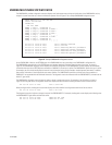
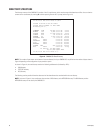
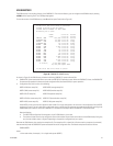
• VGA port: Female DB15 connector that connects to a VGA monitor, which allows you to view system diagnostics. For additional information
about system diagnostics, refer to the System Diagnostics section.
• AT-compatible keyboard port: 5-pin mini DIN connector that connects to the supplied PS/2-to-AT keyboard adapter for connection to the
supplied PS/2 keyboard.
• AC power input connector: Three-prong connector that connects to the supplied power cord. The acceptable power range is 120 VAC to 230
VAC. The power supply automatically adjusts to the proper voltage range.
• Power switch: Rocker-type switch used to power the CM9700-CC1 on or off.
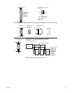
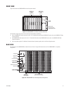
Figure 40 illustrates pinouts of connectors on the rear of the CM9700-CC1.
NOTE: Ports 3 and 4 are not present on the CM9700-CC1.
NOTE: An AT-compatible keyboard port also exists on the front of the CM9700-CC1 behind the front door (refer to Figure 38). Both keyboard
ports cannot be used at the same time.
5
6
7
8
10
9
11
12
19
18
17
16
15
14
1321
22
23
24
25
26
27
28
20
29
30
31
32
33
34
35
36
PRINTER COM1 COM2
PRINTER
PORT*
POWER
INPUT
POWER
SWITCH
AT-COMPATIBLE
KEYBOARD PORT
*RESERVED FOR FUTURE USE
COM 1
PORT
(RS-232)
COM 2
PORT
(RS-232)
VGA
PORT
SERCOM
PORTS
(RS-422)