


C1572M (9/05) 95
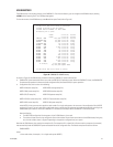
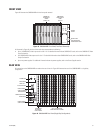
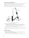
CM9760-VMC Card Guidelines
The following guidelines apply to the CM9760-VMC card:
• The CM9760-VMC card must be installed into slot 17 in the front of the matrix bay. The matrix bay is shipped from the factory with the card
installed in the unit according to the system order.
• The CM9760-VMC card connects to the CM9760-RPM card, which is installed into the associated slot in the rear of the matrix bay.
For information about the CM9760-RPM card, refer to the CM9760-RPM Rear Panel Output Card section.
• S2 DIP switch and X55 and JP2 jumpers are configured properly according to your system order. If you install a new CM9760-VMC card, you
must configure the DIP switch and jumpers as required for your system.
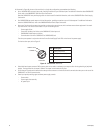
REAR PANEL CARDS
The matrix bay accommodates the following cards, which are installed into the rear of the matrix bay:
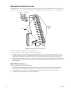
• CM9760-RPC: BNC card for video input connections
• CM9760-RPL: Double-wide BNC card for single-bay looping of video inputs
• CM9760-RPM: BNC card for video output connections
• CM9760-DFC: Downframe card with 32-pin connectors (non-looping)
• CM9760-DFL: Downframe looping BNC card
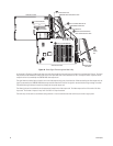
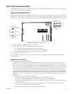
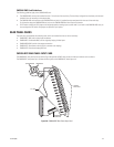
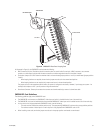
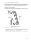
CM9760-RPC REAR PANEL INPUT CARD
The CM9760-RPC rear panel input card (refer to Figure 50) provides 16 BNCs that connect to video input sources such as cameras.
The CM9760-RPC card passes up to 16 external video signals to the CM9760-VCC video input card.
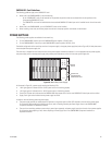
Figure 50. CM9760-RPC Rear Panel Input Card
16 VIDEO
INPUT BNCs
DOWNFRAME
CONNECTOR
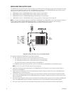
JP1-JP16
UNTERMINATED TERMINATED