


C1572M (9/05) 29
CONNECTING VIDEO INPUTS AND VIDEO OUTPUTS
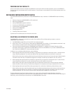
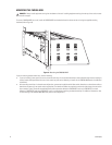
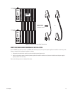
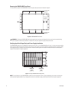
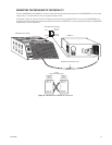
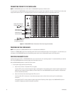
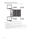
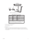
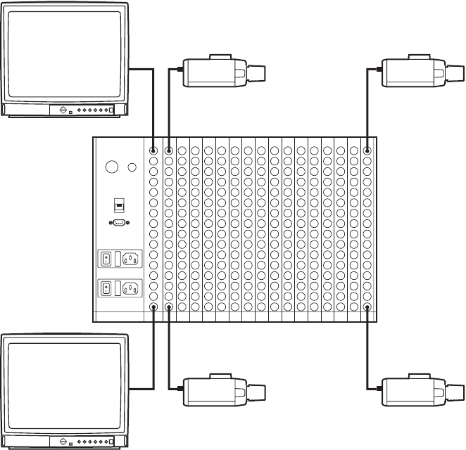
Connect all video inputs (up to 256) and all video outputs (up to 16) to the rear panel BNC cards (refer to Figure 14).
Figure 14. CM9760-MXB Video Input and Output Connections
Note the following:
• To provide adequate ground and signal connections, use crimp-on BNCs rather than screw-on BNCs.
• Allow enough slack in a cable to act as a strain relief between the cable and the BNC connectors.
• Be sure each connection is secure.
• Label all cabling to minimize system downtime if troubleshooting becomes necessary and cabling needs to be disconnected.
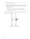
• Video output from the CM9760-VMC video output card is not terminated. Terminate the video signal at the output device (for example,
monitor,VCR, or matrix switcher). If you are looping to other devices, terminate the last device only.
• The endpoint of any video cable run must be teminated in 75 ohms.
• For information about sideframing video inputs and downframing video outputs, refer to Sideframing and Downframing in the
CM9760-MXB Matrix Bay section.
256
241
16
1
1
16
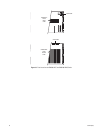
Alarm
Black
Out
RS-422
RS-422