


98 C1572M (9/05)
CM9760-RPM REAR PANEL OUTPUT CARD
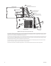
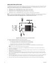
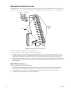
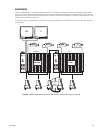
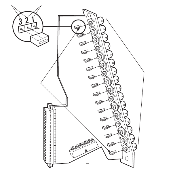
The CM9760-RPM rear panel output card (refer to Figure 52) passes up to 16 video signals from the CM9760-VMC video output card to video
output devices such as monitors, VCRs, and matrix switchers. The CM9760-RPM card provides 16 BNCs that connect to video output devices.
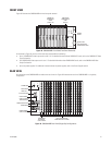
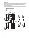
Figure 52. CM9760-RPM Rear Panel Output Card
As illustrated in Figure 52, the CM9760-RPM card includes the following:
• BNC Connectors (16): Provide the physical connection point for coaxial cable
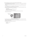
• Termination Jumpers JP1-JP16: Allow video to be terminated (jumper positions 1 and 2) or unterminated (jumper positions 2 and 3).
Note that the termination jumpers on the CM9760-RPM card must always be set in the unterminated position. You must terminate the
video signal at the output device, for example, a monitor or VCR. If you are looping to other devices, terminate the last device only.
• Sideframe Connector: Sixteen-pin connector that connects to a coaxial ribbon cable in a sideframe configuration. A coaxial ribbon cable can
be used instead of coaxial cable connections to the BNC connectors on the CM9760-RPM card. For additional information, refer to the
Sideframing section.
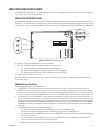
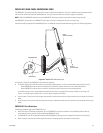
CM9760-RPM Card Guidelines
The following guidelines apply to the CM9760-RPM card:
• The CM9760-RPM card must always be installed into the leftmost slot on the rear of the matrix bay. The leftmost slot provides the
connection point to the CM9760-VMC video output card, which is always inserted into slot 17 in the front of the matrix bay.
• The CM9760-RPM must be installed before the CM9760-VMC video output card is installed into the front of the matrix bay.
• Termination jumpers must always be set in the unterminated position.
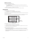
SIDEFRAME
CONNECTOR
16 VIDEO
OUTPUT
BNCs
JP1-JP16
UNTERMINATED TERMINATED