


C1572M (9/05) 21
POWERING ON THE CM9700-CC1
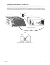
After all system devices have been connected to the CM9700-CC1 and all system devices have been powered on, power on the CM9700-CC1.
To power on the unit, place the power switch in the On (I) position. If, for some reason, you must power off the unit, place the power switch in the
Off (0) position.
INSTALLING CM9760-MXB MATRIX BAY(S)
Your System 9760 installation may include one or multiple CM9760-MXB matrix bays. Installation of a CM9760-MXB includes the following
tasks:
• Selecting a location for the CM9760-MXB in an EIA standard rack
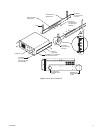
• Mounting the CM9760-MXB
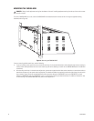
• Verifying CM9760-MXB component installation
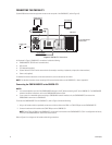
• Connecting the CM9760-MXB to the CM9700-CC1
• Connecting power to the CM9760-MXB
• Powering on the CM9760-MXB
• Checking diagnostic LEDs
• Connecting video inputs and outputs
To perform each of the above tasks, refer to the sections that follow.
SELECTING A LOCATION FOR THE CM9760-MXB
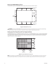
The CM9760-MXB is designed to be mounted into a standard 19-inch (48.26 cm) EIA rack. When selecting a location in a rack for a
CM9760-MXB, note the following:
• The CM9760-MXB occupies 6 RUs or 10.5 inches (26.7 cm) of vertical rack space.
• Allow at least 1 RU or 1.75 inches (4.5 cm) of space above the CM9760-MXB for air circulation. In a high-temperature environment, it may
also be necessary to provide forced air cooling. Contact Product Support for additional information.
• The maximum distance allowable between a CM9760-MXB and the CM9700-CC1 is 4,000 feet (1,219 meters). Note that a 10-foot
(3.05 meters) reversed cable is supplied with the CM9760-MXB for connection to the CM9700-CC1. If you install a CM9760-MXB farther
than 10 feet from the CM9700-CC1, you must create your own cable.
In addition, if you are installing multiple matrix bays, note the following:
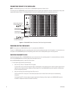
• When expanding video inputs beyond 256 as provided by a single matrix bay, the expansion of video inputs occurs in a horizontal manner
using a sideframing configuration. As a result, each additional matrix bay should be installed at the same level in a nearby rack.
When installing a new system containing multiple matrix bays to be sideframed, note that the rear of each matrix bay is labeled to identify
the location of each matrix bay in the sideframe configuration. For example, the matrix bays are labeled 2A, 12A, 22A, and so on.
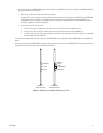
• When expanding video outputs beyond 16 as provided by a single matrix bay, the expansion of video outputs occurs in a vertical manner
using a downframing configuration. As a result, multiple matrix bays must be installed in the same rack.
When installing a new system containing multiple matrix bays to be downframed, note that the rear of each matrix bay is labeled to
identify the location of each matrix bay in the downframe configuration. For example, the matrix bays are labeled 2A, 2B, 2C, and so on.
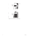
• When expanding video inputs beyond 256 and video outputs beyond 16, a combination of sideframing and downframing is used.
When installing a new system containing multiple matrix bays to be sideframed and downframed, note that the rear of each matrix bay is
labeled to identify the location of each matrix bay in the sideframe and downframe configuration. For example, matrix bays to be side-
framed are labeled 2A, 12A, 22A, and so on; and matrix bays to be downframed are labeled 2B, 12B, 22B, and so on.
To help you determine the location of multiple matrix bays in your system, refer to Appendix B for sample illustrations of matrix bay
configurations. Note the labeling of the matrix bays shown in the sample illustrations. In addition, for detailed information about sideframing and
downframing, refer to Sideframing and Downframing in the CM9760-MXB Matrix Bay section.