


C1572M (9/05) 101
CM9760-DFL Card Guidelines
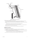
The following guidelines apply to the CM9760-DFL card:
• When used in the CM9760-MXB(-X), note the following:
– Up to 16 CM9760-DFL cards can be inserted into 16 possible slot positions that are associated with the slot positions of the
corresponding CM9760-VCC cards.
– The CM9760-DFL card must be installed before the associated CM9760-VCC video input card is installed into the front of the matrix
bay.
• When used in the CM9769-MXBL, up to 16 CM9760-DFL cards can be installed.
• When installing a new card, termination jumpers must be set in the proper position: terminated or unterminated.
POWER SUPPLIES
The following power supplies are available for the matrix bay:
• For the CM9760-MXB: Contains up to two CM9760-MPS power supplies, 120 VAC, 60 Hz
• For the CM9760-MXB-X: Contains up to two CM9760-MPS-X power supplies, 230 VAC, 50 Hz
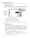
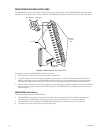
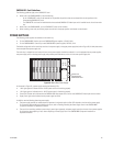
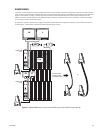
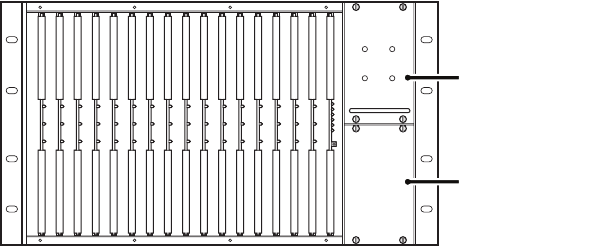
The default configuration of the matrix bay consists of one power supply in the upper power supply slot (refer to Figure 55). A blank plate covers
the unoccupied lower power supply slot.
The matrix bay is shipped from the factory with one or two power supplies installed as ordered. If a unit is equipped with two power supplies,
one power supply acts as a backup power supply and provides power redundancy to the unit if the other power supply fails.
Figure 55. Matrix Bay Power Supply
As illustrated in Figure 55, a power supply contains the following LEDs:
• +10V: Lights green to indicate that the +10 VDC power source is functioning properly.
• -10V: Lights green to indicate that the –10 VDC power source is functioning properly.
• Frame Fault: Flashes red to indicate that the CM9760-VMC video output card or one or more CM9760-VCC video input cards has failed.
• Supply Fault: Lights red to indicate that the power supply has failed.
In addition, note the following about the power supply:
• The power supply provides an audible alarm that operates in conjunction with the Fault LEDs located on the front of the power supply.
For information about enabling and disabling the alarm, refer to Enabling/Disabling the Power Supply Alarm in the CM9760-MXB
Component Installation or Replacement section.
• The rear of the matrix bay provides a power switch, power input receptacle, and power supply input fuses for each of two power supplies.
For information about replacing a fuse, refer to Replacing a Power Supply Fuse in the CM9760-MXB Component Installation or
Replacement section.
+10V -10V
POWER
SUPPLY
BLANK PLATE
FOR UNOCCUPIED
POWER SUPPLY SLOT
FRAME
FAULT
SUPPLY
FAULT
POWER SUPPLY