


C1572M (9/05) 17
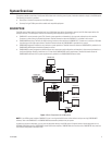
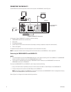
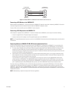
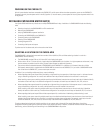
Figure 4.
CM9700-MGR PC to CM9700-CC1 Null Modem Cable Connections
Connecting a VGA Monitor to the CM9700-CC1
When connected to the CM9700-CC1, a VGA monitor displays the CM9700-CC1 diagnostic screen (refer to
Monitoring CM9700-CC1 Functions
in
the
System Diagnostics
section for detailed information about the CM9700-CC1 diagnostic screen).
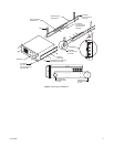
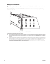
Connect a VGA monitor to the VGA port of the CM9700-CC1 (refer to Figure 3).
Connecting a PS/2 Keyboard to the CM9700-CC1
A PS/2 keyboard is supplied with the CM9700-CC1. To connect the keyboard to the CM9700-CC1, refer to Figure 3 and do the following:
1. Connect the supplied PS/2-to-AT keyboard adapter to the keyboard.
2. Connect the other end of the adapter to the AT-compatible keyboard port on the CM9700-CC1.
NOTE:
An AT-compatible keyboard port also exists on the front of the CM9700-CC1 behind the front door. Both keyboard ports cannot be used at
the same time.
Connecting Devices to CM9700-CC1 RS-422 Serial Communication Ports
RS-422 serial communication ports 5-36, commonly referred to as SERCOM ports, are provided on the CM9700-CC1 for communication with
devices such as matrix bays, keyboards, and pan/tilt or dome receivers. Before connecting devices to the SERCOM ports, note the following:
•
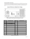
For a new system installation, refer to the System 9760 port assignment table titled “System 9760 Factory Default Port Settings” that is
provided in the System 9760 binder. The port assignment table lists the CM9700-CC1 ports and the particular device that should be
connected to each port as configured at the factory for your system. For additional information about the port assignment table, refer to the
Using the System 9760 Port Assignment Table
section.
•
Certain devices must be connected to SERCOM ports in a particular order based on device priority. In a new system installation that has
been configured at the factory, connecting devices according to the port assignments provided in the System 9760 port assignment table
ensures that you connect the correct device to the correct port.
If you add devices to an existing system, it is recommended that you configure your system using the CM9700-MGR software before
connecting devices to SERCOM ports. The CM9700-MGR software automatically assigns devices to SERCOM ports in the correct order.
By connecting devices according to the port assignments in CM9700-MGR, you ensure that you connect the correct device to the correct
port. For detailed information about SERCOM port device priorities, refer to the
SERCOM Port Device Priority Connections
section.
To connect a device to a SERCOM port, attach an RJ-45 data cable from the device to the appropriate SERCOM port. An RJ-45 data cable is
included with each 9760 system device for connection to the CM9700-CC1. For detailed information about connecting a matrix bay to the
CM9700-CC1, refer to the
Installing CM9760-MXB Matrix Bay(s)
section. For detailed information about connecting an ASCII communication
device to the CM9700-CC1, refer to
Appendix A. For detailed information about connecting other devices to the CM9700-CC1, refer to the manual
supplied with the device.
NOTE: Shielded cabling is required to comply with CE emissions guidelines.
DB9 FEMALE
PIN 5 (GND)
PIN 2 (RX)
PIN 3 (TX)
PIN 3 (TX)
PIN 5 (GND)
PIN 2 (RX)
DB9 FEMALE
NULL MODEM CABLE (RS-232)
TO CM9700-MGR
PC COM 1/COM 2 PORT
TO CM9700-CC1
COM 1/COM 2 PORT