


20 C1572M (9/05)
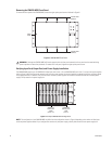
NOTE: If you add matrix bays to an existing system, you may need to change existing port connections to be able to connect each additional
matrix bay to the lowest sequential port possible.
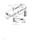
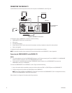
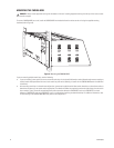
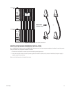
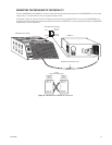
Connecting Power to the CM9700-CC1
To connect power to the CM9700-CC1, connect the supplied 120 VAC or 230 VAC power cord to the power input receptacle on the CM9700-CC1
and to an approved power source.
NOTE: Do not power on the CM9700-CC1 until all system devices have been connected to the CM9700-CC1 and all system devices have been
powered on.
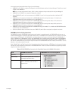
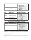
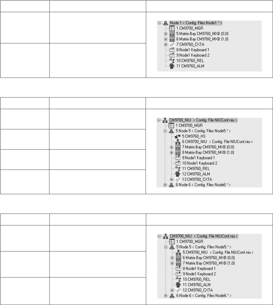
Table B. RS-422 SERCOM Port Connections in a Single-Node System without a CM9760-HS Hot Switch
Device SERCOM Port Connection CM9700-MGR Device Tree Port Assignments
CM9760-MXB(s) Port 5 and next sequential ports as necessary
Other devices Any available ports—connections do not have
to be in sequential ports
Table C. SERCOM Port Connections in a Networked System with a CM9760-HS Hot Switch
Device SERCOM Port Connection CM9700-MGR Device Tree Port Assignments
CM9760-HS Port 5
CM9700-NW1
network interface unit
Port 6—connected through the hot switch
Matrix bay(s) Port 7 and next sequential ports as necessary—
connected through the hot switch
Other devices Any available ports connected through the hot
switch—connections do not have to be in
sequential ports
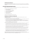
Table D. SERCOM Port Connections in a Networked System without a CM9760-HS Hot Switch
Device SERCOM Port Connection CM9700-MGR Device Tree Port Assignments
CM9700-NW1 network
interface unit
Port 5 on each CM9700-CC1 in the network
Matrix bay(s) Port 6 and next sequential ports as necessary
Other devices Any available ports—connections do not have
to be in sequential ports