


C1572M (9/05) 33
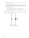
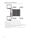
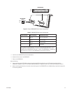
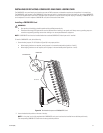
Figure 17. Sample CM9700-SER Card Jumper Assignments
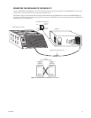
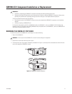
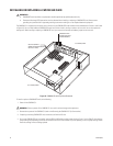
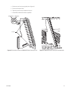
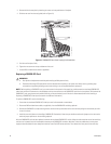
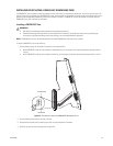
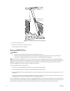
5. Install the new CM9700-SER card into the desired slot.
6. Reattach the front cover of the CM9700-CC1.
7. Power on the CM9700-CC1.
Note the following:
• You can cycle through the IRQ/address settings by toggling the ALT+A key combination on the PC keyboard associated with the
CM9700-CC1 diagnostic screen. (For information about the CM9700-CC1 diagnostic screen, refer to the System Diagnostics section.)
• When connecting system devices to the serial communication ports of the CM9700-SER card, shielded cabling is required to comply with
CE emissions guidelines.
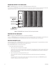
Table E. CM9700-SER Card Jumper Assignments
ISA Slot Number W1 IRQ Setting W2 Address Setting
1 IRQ 10 Pins 1 to 2 and 3 to 4
2 IRQ 11 Pins 1 to 2 only
3 IRQ 12 Pins 3 to 4 only
4* IRQ 5 No jumpers
*The jumper assignments shown for ISA slot 4 are applicable to the CM9700-CC1 but are
not applicable to the CM9700-NW1. A maximum of three CM9700-SER cards can be
installed into the CM9700-NW1 (ISA slots 1, 2, and 3). The CM9700-NW1 is shipped from
the factory with a minimum of one CM9700-SER card installed into ISA slot 1.
IRQ 3
IRQ 4
IRQ 5
IRQ 6
IRQ 7
IRQ 9
IRQ 10
IRQ 11
IRQ 12
IRQ 14
IRQ 15
W1 IRQ SELECT
W2 ADDRESS
SELECT
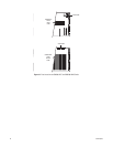
PIN 2
PIN 1
PIN 2
PIN 1
PIN 4
PIN 3
PIN 22
PIN 21