


24 C1572M (9/05)
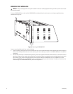
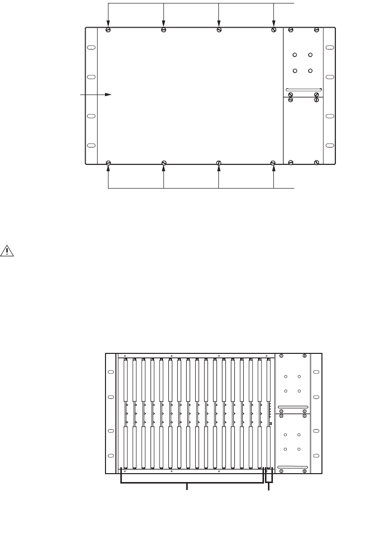
Removing the CM9760-MXB Front Panel
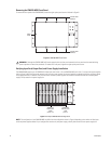
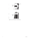
To remove the front panel of the CM9760-MXB, loosen the eight captive panel screws indicated in Figure 8.
Figure 8. CM9760-MXB Front Panel
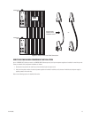
Verifying Input Card, Output Card, and Power Supply Installation
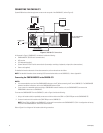
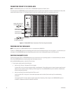
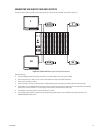
The CM9760-MXB accepts up to 16 CM9760-VCC video input cards in slots 1-16, one CM9760-VMC card in slot 17, and up to two power supplies
(refer to Figure 9). With the front panel removed, verify that the correct number of cards are installed as ordered and that they are firmly seated
in the appropriate slots. In addition, verify that the correct number of power supplies are installed as ordered and that each installed power
supply is firmly seated in the power supply slot.
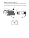
Figure 9. Sample CM9760-MXB Configuration
NOTE: The configuration of your CM9760-MXB may differ from the configuration shown in Figure 9 depending on the number of video input
cards and power supplies ordered. If your configuration contains only one power supply, a blank plate covers the lower power supply slot.
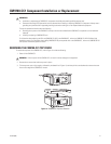
WARNING: Although the CM9760-MXB will function properly with the front panel removed, the front panel must be attached during
system operation to meet safety standards. To reattach the front panel, tighten the eight captive panel screws.
CAPTIVE PANEL
SCREW (4)
FRONT
PANEL
CAPTIVE PANEL
SCREW (4)
+10V
FRAME
FAULT
SUPPLY
FAULT
-10V
+10V
FRAME
FAULT
SUPPLY
FAULT
-10V
CM9760-VCC
VIDEO INPUT
CARDS
(SLOTS 1-16)
CM9760-VMC
VIDEO OUTPUT
CARD
(SLOT 17)