


C1572M (9/05) 37
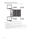
INSTALLING OR REPLACING A CM9760-RPL REAR PANEL LOOPING CARD
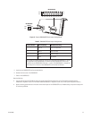
The CM9760-RPL rear panel looping card contains two rows of BNC connectors and therefore occupies two slot positions in the matrix bay.
The CM9760-RPL card connects to one CM9760-VCC video input card, which is installed into the front of the matrix bay. Up to eight CM9760-RPL
cards can be installed when a maximum of 128 video inputs is required in a system that also requires looping. If necessary, a CM9760-RPL card
can be replaced. To install or replace a CM9760-RPL card, refer to the sections that follow.
Installing a CM9760-RPL Card
NOTE: A CM9760-RPL card must be installed before the associated CM9760-VCC video input card is installed.
To install a CM9760-RPL card, do the following:
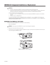
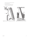
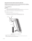
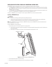
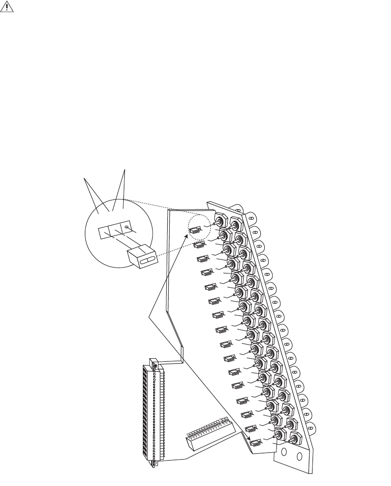
1. Set termination jumpers JP1-JP16 (refer to Figure 20) in the proper position:
• When looping functions are required, set the jumpers in the unterminated position (positions 2 and 3).
• When looping functions are not required, set the jumpers in the terminated position (positions 1 and 2).
Figure 20. Termination Jumpers on CM9760-RPL Card
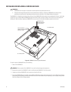
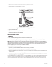
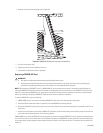
2. Locate the desired slot position at the rear of the bay.
WARNINGS:
• Rear panel card installation should be performed by qualified personnel only.
• Electrostatic discharge (ESD) precautions must be observed when installing a rear panel card. Always wear a grounding strap con-
nected to an approved grounding source when working on or near exposed electronic equipment.
NOTE: In a bay that is to be fully populated with CM9760-RPL cards, each card must be installed into an odd slot position only.
The corresponding CM9760-VCC cards must also occupy odd slot positions.
3
2
1
UNTERMINATED
TERMINATED
JP1-JP16