


C1572M (9/05) 27
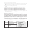
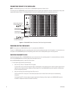
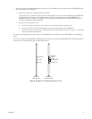
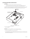
2. With the front panel of the CM9760-MXB removed, check the LEDs on the CM9760-VCC video input cards and on the CM9760-VMC video
output card as follows (refer to Figure 12):
a. Verify that all +10 VDC and –10 VDC power LEDs are lit (green).
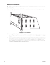
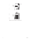
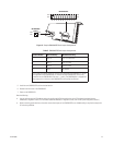
If a power LED is not lit, remove the card and inspect the fuses (refer Figure 13 for fuse locations on CM9760-VCC and CM9760-VMC
cards). Replace fuse(s) if necessary. If the condition continues, replace the card. For instructions to replace a CM9760-VCC or
CM9760-VMC card, refer to Replacing a CM9760-VCC Card or to Replacing a CM9760-VMC Card in the CM9760-MXB Component
Installation or Replacement section as applicable.
b. Verify that all Comm Fail LEDs are not lit:
• If the LED is lit (red) on any video input card, reseat the card. If the condition continues, replace the card.
• If the Comm Fail LED is lit (red) on the video output card only, check the communication to the CM9700-CC1.
• If all Comm Fail LEDs are lit (red), press the Reset button located on the video output card (refer to Figure 12). If the problem
continues, replace the video output card.
For a summary of troubleshooting information relating to the CM9760-MXB, refer to Troubleshooting the CM9760-MXB in the Troubleshooting
section.
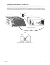
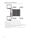
After you have verified that the CM9760-MXB is operating properly, reattach the front panel of the CM9760-MXB. Then connect video inputs and
outputs (refer to the Connecting Video Inputs and Video Outputs section).
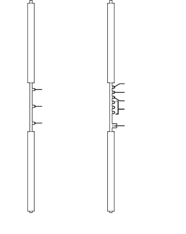
Figure 12. CM9760-VCC and CM9760-VMC Diagnostic LEDs
+10 VDC
-10 VDC
COMM FAIL
RESET BUTTON
COMM FAIL
+10 VDC
-10 VDC
NO ASSIGNMENT
CM9760-VCC
VIDEO INPUT CARD
CM9760-VMC
VIDEO OUTPUT CARD