


94 C1572M (9/05)
CM9760-VMC VIDEO OUTPUT CARD
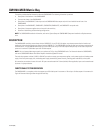
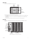
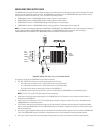
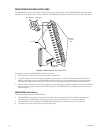
The CM9760-VMC video output card (refer to Figure 49) routes up to 16 video signals from the video bus, adds idents (if applicable), and routes
the signals to video outputs (for example, monitors). The CM9760-VMC card contains up to 16 CM9760-VMM video output modules—each of
which provides one video output with titling—and is available in the following models:
• CM9760-VMC4 contains 4 CM9760-VMM modules, providing support for 4 video outputs.
• CM9760-VMC8 contains 8 CM9760-VMM modules, providing support for 8 video outputs.
• CM9760-VMC12 contains 12 CM9760-VMM modules, providing support for 12 video outputs.
• CM9760-VMC16 contains 16 CM9760-VMM modules, providing support for 16 video outputs (refer to Figure 49).
NOTE: The number of video outputs supported by CM9760-VMC4, CM9760-VMC8, and CM9760-VMC12 cards can be expanded to a maximum
of 16 by installing additional CM9760-VMM video output modules. For CM9760-VMM installation instructions, refer to Installing a
CM9760-VMM Video Output Module in the CM9760-MXB Component Installation or Replacement section.
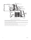
Figure 49. CM9760-VMC Video Output Card (CM9760-VMC16)
As illustrated in Figure 49, the CM9760-VMC card includes the following:
• DS4, DS5, and DS6 LEDs: Allow you to monitor the operating status of the card:
– DS4: Lights green to indicate that the +10 VDC power source is functioning properly.
– DS5: Lights green to indicate that the –10 VDC power source is functioning properly.
– DS6: Lights red to indicate a communication failure with the CM9700-CC1.
For troubleshooting information relating to the LEDs, refer to Troubleshooting the CM9760-MXB in the Troubleshooting section.
• Reset Button: Pressing the button resets operation of the CM9760-VMC card. All information, such as camera and monitor idents, is
reloaded from the CM9700-CC1.
• Power Fuses: Two 0.7ASB fuses (F6 and F7). For troubleshooting information relating to the power fuses, refer to Troubleshooting the
CM9760-MXB in the Troubleshooting section.
• S2 DIP Switch: Determines the communication baud rate, the video standard, and whether video loss detection is enabled or disabled.
Refer to Installing a CM9760-VMC Card in the CM9760-MXB Component Installation or Replacement section for S2 DIP switch functions
and associated settings.
• X55 Jumper: Eight-pin header that determines the video standard for video black generator operation. Refer to Installing a CM9760-VMC
Card in the CM9760-MXB Component Installation or Replacement section for video standards and associated jumper positions.
• JP2 Jumper: Two-pin header that controls the program loading sequence. A jumper must always be installed for proper operation.
NOTE: The DS1, DS2, and DS3 LEDs light amber but have no assignment.
ON
1 2 3 4
S2
F6
F7
X55
JP2
VIDEO
OUTPUT
MODULES
RED DS6
GREEN DS5
GREEN DS4
DS3
AMBER DS2
DS1
RESET
SWITCH