


90 C1572M (9/05)
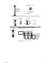
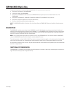
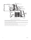
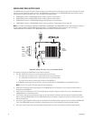
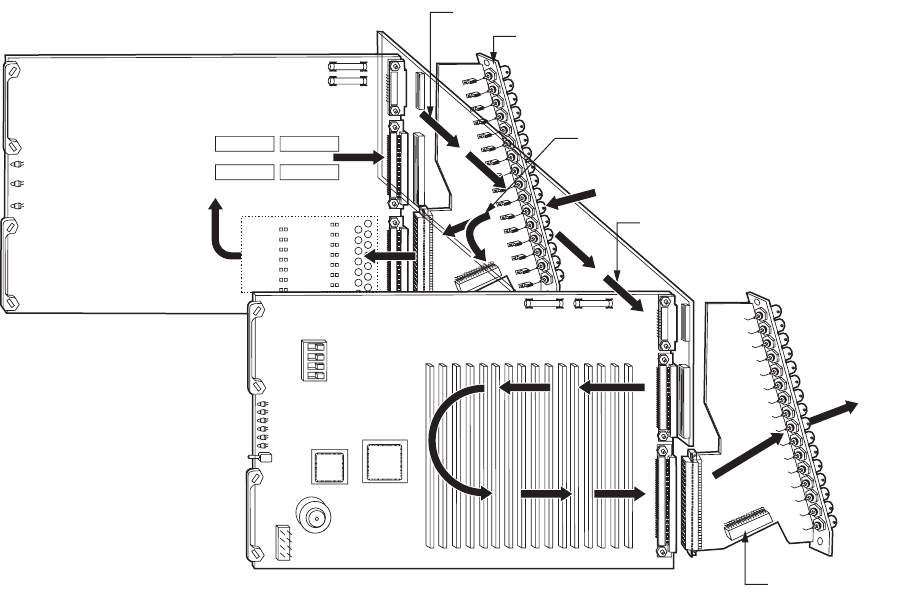
Figure 44. Video Signal Flow through the Matrix Bay
As illustrated in Figure 44, a video signal enters the matrix bay through the rear panel input card where it is terminated with 75 ohms. The signal
then proceeds to the CM9760-VCC video input card via the input buffer and is then directed to the 16 x 16 crosspoint switch. Operation of the
crosspoint switch is controlled by the CM9760-VMC video output card.
The signal leaves the video input card and is sent to the video output card by way of the video bus. When received by the video output card, the
signal is processed by the CM9760-VMM video output module where the DC level of the signal is restored and the titling message is inserted.
The edited video signal leaves the matrix bay through the rear panel output card.
The video signal path is controlled by the microprocessor located on the video output card. The video output card has full control of all video
input cards. The number of inputs can vary from 16 to 256 in 16-input increments.
The matrix bay can be used as a standalone routing switcher or it can be connected to other matrix bays to create a larger system.
ᕡ
ᕦ
ᕨ
ᕥ
ᕢ
ᕤ
ᕣ
ᕧ
VIDEO OUTPUT BUS
REAR PANEL VIDEO INPUT CARD
VIDEO SIGNAL IN
SIGNAL ON BACKPLANE ON
WAY TO VIDEO OUTPUT CARD
REAR PANEL
BNC CARD
VIDEO
SIGNAL
OUT
VIDEO OUTPUT CARD
OUTPUT TITLING MODULE
INPUT BUFFER
VIDEO INPUT CARD
16x16 CROSSPOINT
PATH TO VIDEO CARD AND TO
DOWNFRAME CONNECTOR