


92 C1572M (9/05)
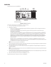
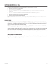
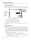
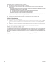
As illustrated in Figure 46, the rear of the matrix bay in a single-bay configuration accommodates the following:
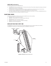
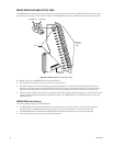
• Up to 16 CM9760-RPC rear panel input cards, providing connection to up to 256 video inputs. For additional information about CM9760-RPC
cards, refer to the CM9760-RPC Rear Panel Input Card section.
Note that CM9760-RPL rear panel looping cards can also be used. For detailed information, refer to the CM9760-RPL Rear Panel Looping
Card section.
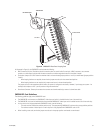
• One CM9760-RPM rear panel output card in the leftmost slot, providing connection to up to 16 video outputs. For additional information
about the CM9760-RPM card, refer to the CM9760-RPM Rear Panel Output Card section.
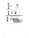
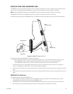
• Alarm port: Four-pin audio connector that provides an alarm relay contact closure, which activates remote alarm equipment if the matrix
bay malfunctions. The contact closure closes if any of the following occurs:
– Power supply failure
– Frame fault including fuse failure on the CM9760-VCC video input card
– CM9760-VMC video output card failure
– Communication fault with a CM9760-VCC or CM9760-VMC card
The alarm port operates in conjunction with the Frame Fault and Supply Fault LEDs on the front of the power supply.
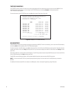
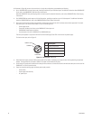
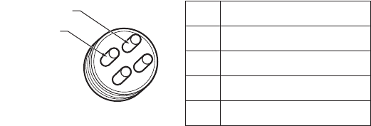
To wire the alarm port, refer to Figure 47.
Figure 47. CM9760-MXB Alarm Port
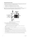
• Video black level output connector: BNC connector that can be used as a reference sync output to allow for the genlocking of peripheral
devices. The signal level for the output is 300 mV. The output is terminated with 75 ohms.
• RJ-45 data port: Female serial communication data port that connects to a female RJ-45 serial communication data port on the rear of the
CM9700-CC1 for RS-422 communication.
• Power input panels providing upper and lower power supply controls:
– Power switch
– Power supply fuse assembly
– AC power input
COMMON
NORMALLY OPEN
ALARM PORT
Pin Description
1 Relay One Common
2 Relay One Normally Open
3 Not Used
4 Not Used