


C1572M (9/05) 89
CM9760-MXB Matrix Bay
This section provides detailed information about the CM9760-MXB. The following information is provided:
• Description of the functions of the CM9760-MXB
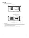
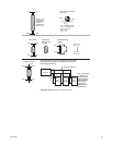
• Front and rear views of the CM9760-MXB
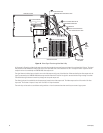
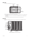
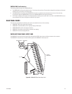
• Description of the CM9760-VCC video input card and CM9760-VMC video output card, which are installed into the front of the
CM9760-MXB
• Description of the CM9760-RPC, CM9760-RPL, CM9760-RPM, CM9760-DFC, and CM9760-DFL rear panel cards
• Description of the power supplies that can be used in the matrix bay
• Overview of sideframing and downframing configurations
NOTE: For CM9760-MXB installation information, refer to the System Setup and CM9760-MXB Component Installation or Replacement sec-
tions.
DESCRIPTION
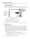
The CM9760-MXB matrix bay communicates with the CM9700-CC1 via an RS-422, full-duplex, asynchronous communication interface and
performs all video switching functions as directed from the CM9700-CC1. The CM9760-MXB provides all video input and output connections for
the 9760 system. A single CM9760-MXB accepts up to 256 video inputs and up to 16 video outputs. Multiple bays can be used to expand the
system to a maximum of 2,048 video inputs and 128 video outputs.
NOTE: You can increase video output capacity to a maximum of 512 by using CM9760-MDA units. For information about the CM9760-MDA,
refer to the CM9760-MDA Master Distribution Amplifier Installation/Operation manual.
The matrix bay operates on either 120 VAC or 230 VAC input and can accept up to two power supplies: a main power supply and a backup power
supply. If the main power supply fails, the backup power supply automatically powers the unit, providing power redundancy to the system.
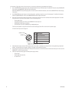
All connections are made on the rear of the unit. All inputs are terminated with 75 ohms (default). When applicable, inputs can be unterminated
by means of a jumper selection.
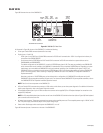
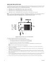
FUNCTIONAL SYSTEM OVERVIEW
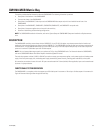
The CM9760-MXB is a crosspoint switch that supports up to 256 video inputs in increments of 16 and up to 16 video outputs in increments of 4.
Figure 44 illustrates video signal flow through the matrix bay.