


16 C1572M (9/05)
CONNECTING THE CM9700-CC1
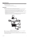
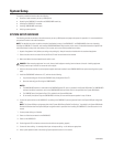
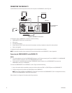
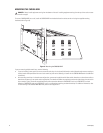
System 9760 devices and other equipment connect to the rear panel of the CM9700-CC1 (refer to Figure 3).
Figure 3.
CM9700-CC1 Connections
As illustrated in Figure 3, CM9700-CC1 connections include the following:
•
CM9700-MGR PC (RS-232 serial communication)
•
VGA monitor
•
PS/2 keyboard (supplied)
•
System devices for RS-422 serial communication (for example, matrix bays, keyboards, and pan/tilt or dome receivers)
•
Power cord (supplied)
For detailed information about each of the above connections, refer to the sections that follow.
NOTE:
For detailed information about connecting ASCII communication devices to the CM9700-CC1, refer to
Appendix A.
Connecting the CM9700-MGR PC to the CM9700-CC1
NOTES:
•
It is recommended that you install the CM9700-MGR software on the PC before connecting the PC to the CM9700-CC1. For CM9700-MGR
software installation instructions, refer to the CM9700-MGR Software Guide.
•
If your system is a networked system containing a CM9700-NW1 network interface unit, the CM9700-MGR PC connects to the
CM9700-NW1 rather than to a CM9700-CC1.
To connect the CM9700-MGR PC to the CM9700-CC1, refer to Figure 3 and do the following:
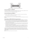
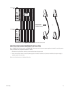
1. Using a null modem cable (not provided), connect one end of the cable to the COM 1 or COM 2 DB9 port on the CM9700-MGR PC.
2. Connect the other end of the cable to the COM1 DB9 port on the CM9700-CC1.
Refer to Figure 4 for a diagram of null modem cable wiring connections.
NOTE:
Either COM 1 or COM 2 on the CM9700-CC1 can be used for connection to the CM9700-MGR PC. COM 1 is configured at the factory
for use with the CM9700-MGR PC and RS-232 communication.
COM1PRINTER COM2
5
6
7
8
10
9
11
12
19
18
17
16
15
14
1321
22
23
24
25
26
27
28
20
29
30
31
32
33
34
35
36
CM9700-MGR PC
VGA MONITOR
CM9700-CC1
PS/2 KEYBOARD
POWER CORD
RS-422 SERCOM PORT
CONNECTIONS