34 C1572M (9/05)
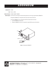
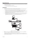
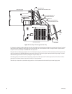
CM9760-MXB Component Installation or Replacement
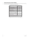
This section provides information about the following:
• Installing or replacing rear panel cards (CM9760-RPC, CM9760-RPL, CM9760-DFC, CM9760-DFL, and CM9760-RPM)
• Installing or replacing a CM9760-VCC video input card
• Installing or replacing a CM9760-VMC video output card
• Installing a CM9760-VMM module on a CM9760-VMC video output card
• Installing or replacing a power supply
• Replacing a power supply fuse
In addition, this section also provides information about enabling/disabling the power supply alarm.
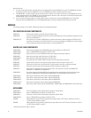
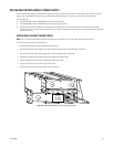
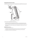
INSTALLING OR REPLACING REAR PANEL CARDS
CM9760-RPC, CM9760-RPL, CM9760-DFC, CM9760-DFL, and CM9760-RPM cards are installed into the rear of the matrix bay. For an initial
system installation, the cards are installed at the factory as ordered. Rear panel cards (and associated front panel cards) can be added to expand
a system or can be replaced if necessary.
NOTE: Rear panel cards must be installed before the associated CM9760-VCC video input card or CM9760-VMC video output card is installed
into the front of the matrix bay.
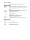
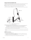
INSTALLING OR REPLACING A CM9760-RPC REAR PANEL INPUT CARD
Up to 16 CM9760-RPC cards can be installed into 16 possible slot positions that are associated with the slot positions of the corresponding
CM9760-VCC cards to be installed. If necessary, a CM9760-RPC card can be replaced. To install or replace a CM9760-RPC card, refer to the
sections that follow.
Installing a CM9760-RPC Card
NOTE: A CM9760-RPC card must be installed before the associated CM9760-VCC video input card is installed.
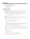
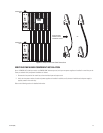
To install a CM9760-RPC card, do the following:
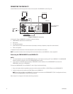
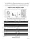
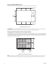
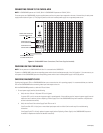
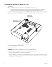
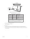
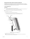
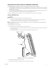
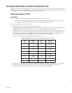
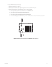
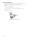
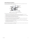
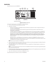
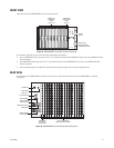
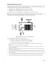
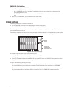
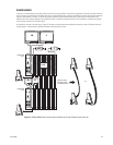
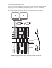
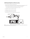
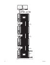
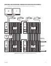
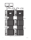
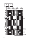
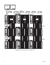
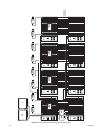
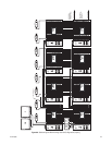
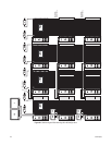
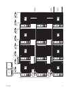
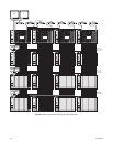
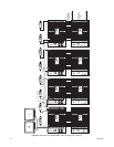
1. Set termination jumpers JP1-JP16 (refer to Figure 18) in the proper position:
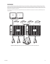
• In a single-bay configuration, the setting of the jumpers depends on whether video is to be looped to another device (for example, a
DVR, VCR, or matrix switcher):
– When looping is not required, set the jumpers in the terminated position (jumper positions 1 and 2) (default setting).
– When looping is required, set the jumpers in the unterminated position (jumper positions 2 and 3).
• In multiple-bay configurations, set the jumpers in the unterminated position.
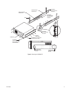
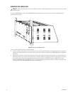
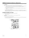
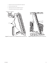
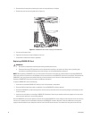
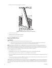
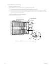
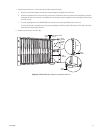
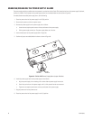
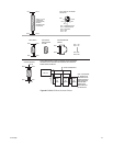
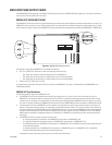
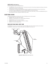
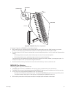
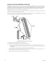
2. Locate the desired slot position at the rear of the bay.
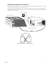
3. Remove the blank cover plate by loosening the screw at the top and bottom of the plate.
WARNINGS:
• Installation or replacement of CM9760-MXB components should be performed by qualified personnel only.
• Electrostatic discharge (ESD) precautions must be observed when installing or replacing CM9760-MXB components. Always wear a
grounding strap connected to an approved grounding source when working on or near exposed electronic equipment.
WARNINGS:
• Rear panel card installation should be performed by qualified personnel only.
• Electrostatic discharge (ESD) precautions must be observed when installing a rear panel card. Always wear a grounding strap
connected to an approved grounding source when working on or near exposed electronic equipment.
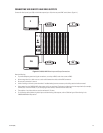
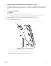
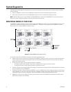
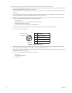
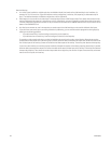
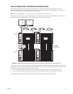
NOTE: The physical number of a video input is determined by the position of the CM9760-VCC card, which is installed into the front of the
matrix bay. Viewed from the rear of the matrix bay, slot 1 is located on the right and corresponds to physical input numbers 1-16, slot 2
corresponds to physical input numbers 17-32, and so on. As a result, if you do not install CM9760-RPC cards in sequential order, be sure to
use the correct physical input number when programming the system using the CM9700-MGR.