


C1572M (9/05) 91
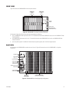
FRONT VIEW
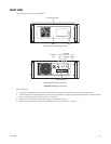
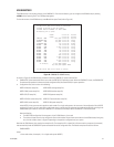
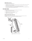
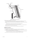
Figure 45 illustrates the CM9760-MXB with the front panel removed.
Figure 45. CM9760-MXB Front View (Front Panel Removed)
As illustrated in Figure 45, the front of the matrix bay accommodates the following:
• Up to 16 CM9760-VCC video input cards in slots 1-16. For detailed information about CM9760-VCC cards, refer to the CM9760-VCC Video
Input Card section.
• One CM9760-VMC video output card in slot 17. For detailed information about CM9760-VMC cards, refer to the CM9760-VMC Video
Output Card section.
• Up to two power supplies. For additional information about the power supplies, refer to the Power Supplies section.
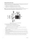
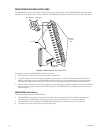
REAR VIEW
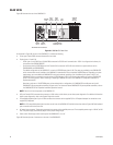
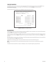
All connections to the CM9760-MXB are made to the rear of the unit. Figure 46 illustrates the rear of the CM9760-MXB in a single-bay
configuration.
Figure 46. CM9760-MXB Rear View (Single-Bay Configuration)
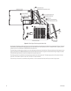
+10V -10V
CM9760-VCC
VIDEO INPUT
CARDS
(SLOTS 1-16)
CM9760-VMC
VIDEO OUTPUT
CARD
(SLOT 17)
POWER
SUPPLY
BLANK PLATE
FOR UNOCCUPIED
POWER SUPPLY SLOT
FRAME
FAULT
SUPPLY
FAULT
POWER SUPPLY
Alarm
POWER SWITCH
VIDEO BLACK
LEVEL OUT
ALARM PORT
RJ-45 DATA PORT
POWER SUPPLY FUSE
POWER INPUT
CM9760-RPM
REAR PANEL
OUTPUT CARD
UP TO 16 CM9760-RPC
REAR PANEL INPUT CARDS
RS-422
RS-422
LOWER POWER
SUPPLY CONTROLS
UPPER POWER
SUPPLY CONTROLS
Black
Out