


18 C1572M (9/05)
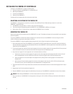
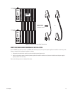
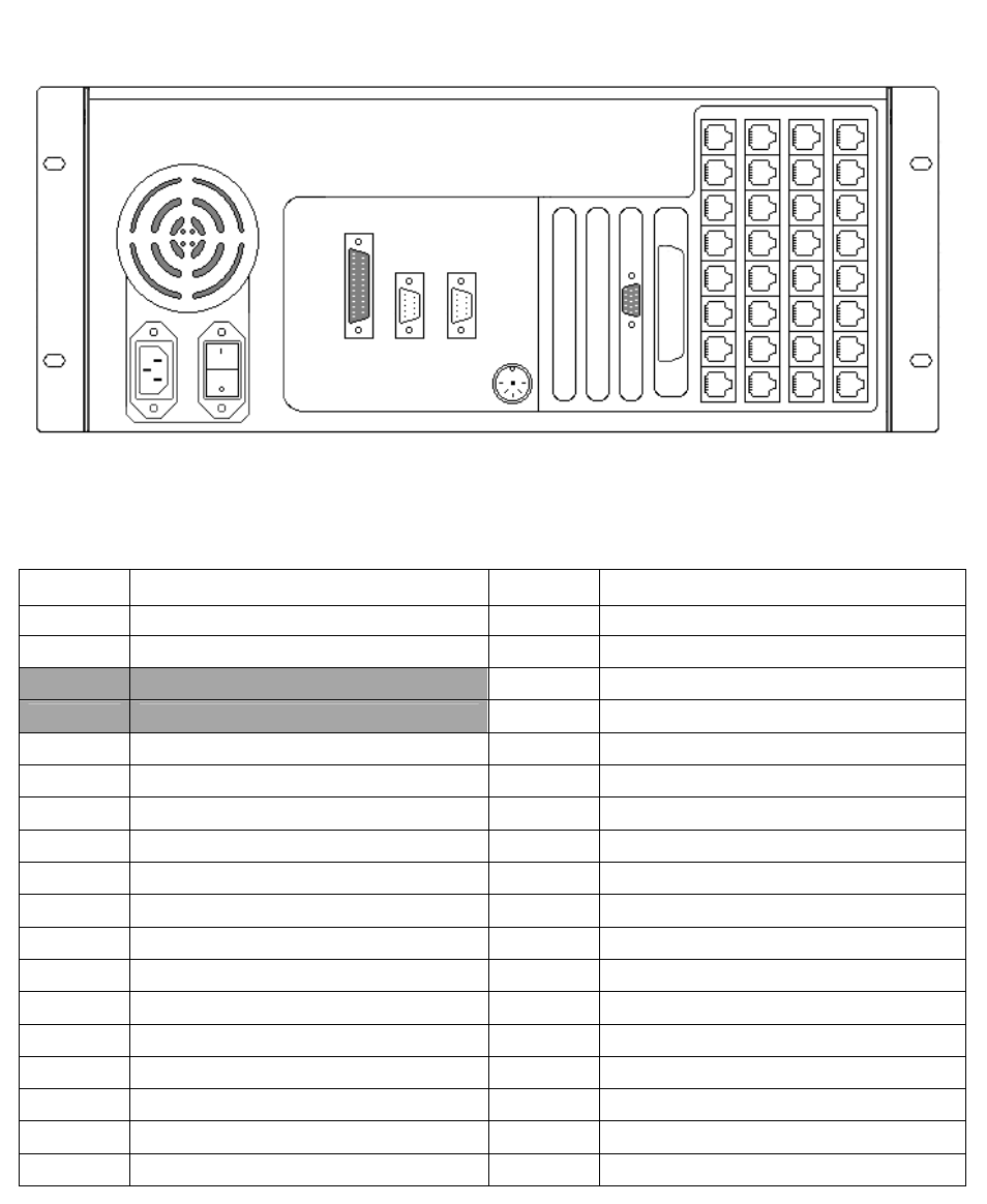
Using the System 9760 Port Assignment Table
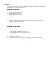
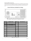
The System 9760 port assignment table, titled “System 9760 Factory Default Port Settings,” lists the CM9700-CC1 port numbers (1-36) and each
device that has been assigned to a particular CM9700-CC1 port and configured for your system at the factory. Figure 5 illustrates a sample port
assignment table for a system containing a CM9700-MGR (System Manager) PC, three CM9760-MXBs, and one CM9760-KBD. Note that the port
assignment table for your system will differ from the one shown in Figure 5 depending on the types and number of devices included in your
system.
Figure 5. Sample Port Assignment Table
System 9760 Factory Default Port Settings
Note: The number of ports on your system may differ from the
above drawing. Connect System 9760 components as follows:
PORT
DESCRIPTION PORT DESCRIPTION
1(RS-232)
SYSTEM MANAGER
19
2(RS-232) 20
3
NOT AVAILABLE
4
NOT AVAILABLE
5
CM9760-MXB (2A) (OUTPUTS 1-16)
23
6
CM9760-MXB (2B) (OUTPUTS 17-32)
24
7
CM9760-MXB (2C) (OUTPUTS 33-48)
25
8
CM9760-KBD (PIN 1111)
26
927
10 28
11 29
12 30
13 31
14 32
15 33
16 34
17 35
18 36
36
35
34
33
32
31
30
29
28
27
26
25
24
23
22
21
20
19
18
17
16
15
14
13
12
11
10
9
8
7
6
5
PRINTER COM1 COM2