


14 C1572M (9/05)
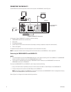
INSTALLING THE CM9700-CC1 CONTROLLER
Installation of the CM9700-CC1 includes the following tasks:
•
Selecting a location for the CM9700-CC1 in a standard EIA rack
•
Mounting the CM9700-CC1
•
Connecting the CM9700-CC1
•
Powering on the CM9700-CC1
To perform each of the above tasks, refer to the sections that follow.
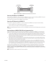
SELECTING A LOCATION FOR THE CM9700-CC1
The CM9700-CC1 is designed to be mounted into a standard 19-inch (48.26 cm) EIA rack. When selecting a location in a rack for the
CM9700-CC1, note the following:
•
The CM9700-CC1 occupies 4 RUs or 7 inches (17.78 cm) of vertical rack space.
•
The maximum distance allowable between the CM9700-CC1 and a CM9760-MXB is 4,000 feet (1,219 meters).
•
Allow at least 1 RU or 1.75 inches (4.5 cm) of space above the CM9700-CC1 for air circulation.
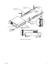
MOUNTING THE CM9700-CC1
Brackets and support rails are provided to mount the CM9700-CC1 into a rack. The brackets and support rails are provided for your convenience
but are not required.
To mount the CM9700-CC1 without the brackets and support rails, fasten each rack ear of the CM9700-CC1 to the rack using two 10-32 x
0.750-inch Phillips pan head screws and washers for each ear.
To mount the CM9700-CC1 using the supplied brackets and support rails, refer to Figure 2 and perform the following steps:
1. Attach one bracket to each side of the CM9700-CC1 using three 8-32 x 0.250-inch pan head screws for each side. Attach each bracket so
that the slotted holes in the bracket are positioned toward the front of the CM9700-CC1 and the tapered ends of the bracket are positioned
toward the rear of the CM9700-CC1.
2. For each set of support rails, attach the front-mounting support rail to the rear-mounting support rail using three 8-32 x 0.375-inch pan head
screws and washers for each set. Leave the screws loose until the support rails are attached to the rack.
3. Attach one set of support rails to the equipment rack in the desired location as follows:
a. Position the ear of the front-mounting support rail against the front of the equipment rack and align the holes in the ear of the rail
with the threaded holes in the rack. Attach the ear of the rail to the rack using two 10-32 x 0.375-inch flat head screws.
b. Adjust the support rails to the correct depth of the equipment rack by sliding the rear-mounting support rail to the back of the
equipment rack.
c. Attach the ear of the rear-mounting support rail to the rear of the equipment rack using four 10-32 x 0.375-inch flat head screws.
(The holes in the ear of the rail should align with the threaded holes in the equipment rack.)
4. Tighten the three 8-32 x 0.375-inch pan head screws and washers that were attached to the front- and rear-mounting support rails in step 2
above.
5. Repeat steps 3 and 4 for the second set of support rails.
6. Place the CM9700-CC1 onto the support rails and slide the unit into the rack. The CM9700-CC1 should slide in and out of the rack easily.
7. Fasten each rack ear of the CM9700-CC1 to the equipment rack using two 10-32 x 0.750-inch Phillips pan head screws and washers for
each ear.
DANGER:
When sliding the CM9700-CC1 out of the rack, be careful not to let the unit fall out of the rack.