


Using Features and Options
11-4
EATON Powerware
®
9390 UPS (100–160 kVA) Installation and Operation Manual S 164201604 Rev B powerware.com
11.4 Relay Interface Module II
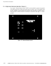
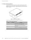
An optional RIM II uses relay contact closures to indicate the operating status and alarm
condition of the UPS system. The RIM II can be flush-mounted or surface-mounted on a
desktop, or secured to a wall. Figure 11-2 shows the RIM II with its four 15-pin connectors
labeled J1 through J4.
Figure 11-2. Relay Interface Module II
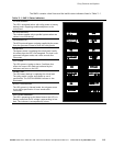
The RIM II can provide the status and alarm signals shown in Table 11-2.
Table 11- 2. Customer Interface Connectors
Status J1 through J4 Description
UPS AVAILABLE
Pins 1 and 12 Contacts are closed when the UPS is operating in
Normal mode or ready to supply the load.
UPS OFFLINE
Pins 3 and 13 Contacts are open when the UPS is offline.
Contacts are closed when the UPS is operating in
Normal mode.
BATTERY WEAK
Pins 5 and 14 Contacts are closed when approximately two minutes of
battery time is remaining, before the critical load is lost.
UTILITY FAILURE
Pins 6 and 15 Contacts are closed when Utility Failure is detected.