


Installing a Remote Emergency Power-off Switch
5-2
EATON Powerware
®
9390 UPS (100–160 kVA) Installation and Operation Manual S 164201604 Rev B powerware.com
6. Remove the screws securing the internal panel covering the TB1 and TB2 terminal
blocks at the top of the UPS cabinet (see Drawing 164201604-8 starting on
page A-33).
7. If installing interface wiring from the bottom of the cabinet, proceed to Step 8;
otherwise, proceed to Step 10.
8. Remove the screws securing the top internal safety shield panel and open the
panel to gain access to the b ottom wiring entry.
9. Remove the screws securing the bottom internal safety shield panel and remove
the panel to gain access to the bottom conduit landing plate.
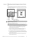
10. To locate the appropriate terminals and review the wiring and termination
requirements, see Figure 5-1 and Drawing 164201604-8 starting on page A-33.
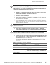
11. Route and connect the wiring as shown in Table 5-1 and Table 5-2.
12. If a normally-closed EPO switch is not used, ensure a jumper wire is connected
between pins 1 and 2 on UPS TB1.
Table 5-1. REPO Wire Terminations
From REPO Station(s) To Customer Interface
Terminal Board TB1 in UPS Cabinet
Remarks
TB1-4 TB-3
Twisted Wires (2)
14–22 AWG
TB1-5 TB-4
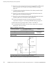
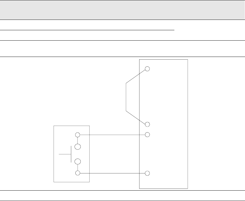
Table 5-2. REPO
5 4 (COMMON)
1(NC)
UPS TB1
REPO
Switch
(NO)
Twisted
Wires
2 (COMMON)
3(NO)
4
(LATCHING-TYPE
SWITCH ONLY)
REPO switch rating is 24 Vdc. 1A minimum if supplied by customer.
NOTE The REPO switch must be a latching-type switch with a dedicated circuit.