


032406B
164201604---8
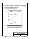
DESCRIPTION:
DATE:
DRAWING NO: SHEET:
REVISION:
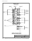
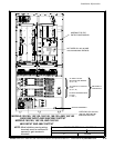
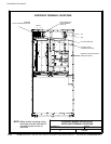
INTERFACE WIRING I NSTALLATION
NOTES AND TERMINAL LO CATIONS
6of13
Installation Information
A-38
EATON Powerware
®
9390 UPS (100–160 kVA) Installation and Operation Manual S 164201604 Rev B powerware.com
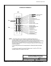
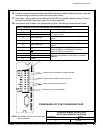
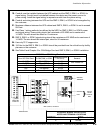
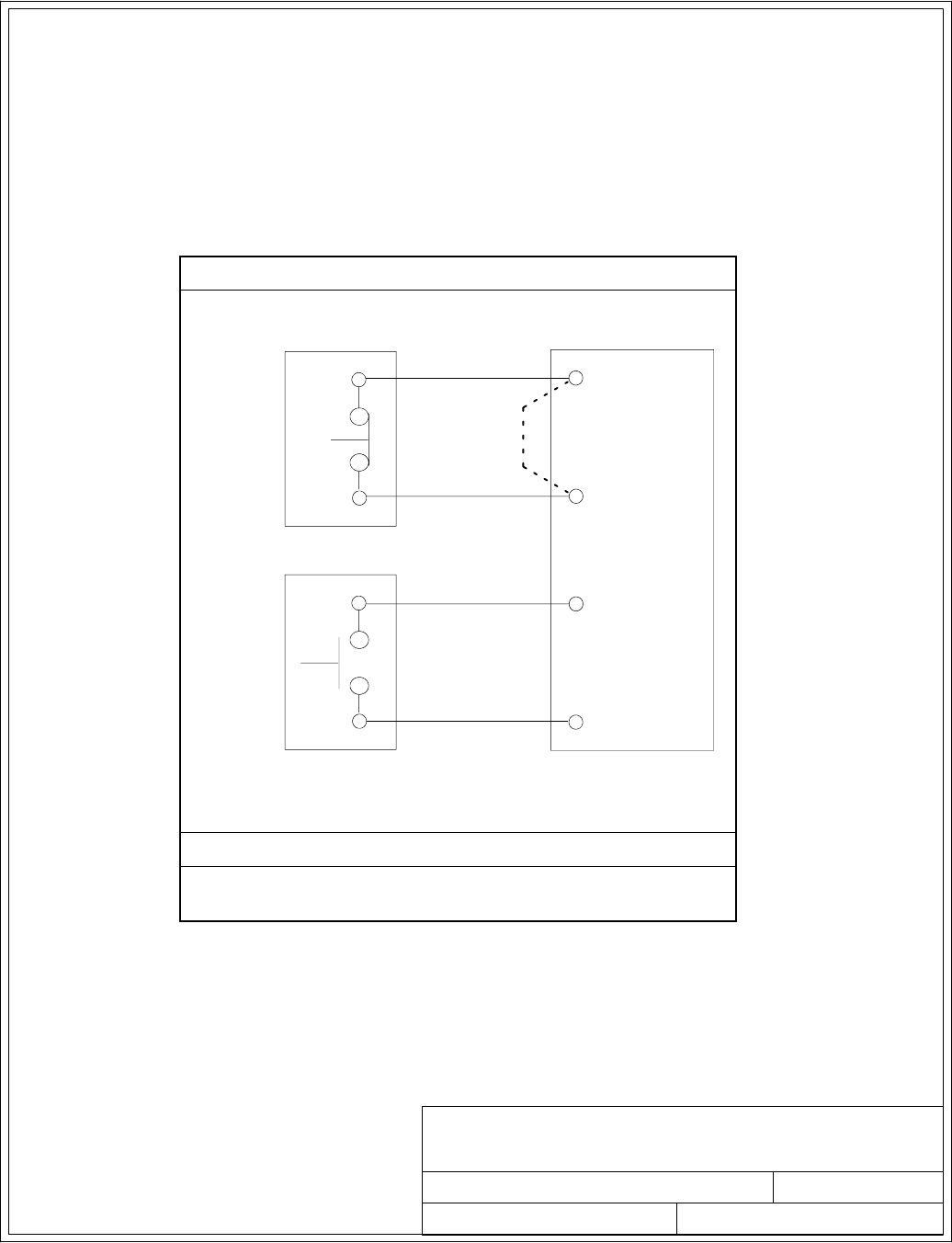
11. The Remote EPO feature opens all contactors in the UP S cabinet and isolates power from
your critical load. Local electrical codes may also require tripping upstream protective
devices to the UPS. This switch must be a dedicated latching-type switch not tied into a ny
other circuit.
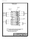
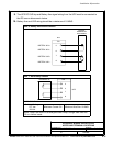
12. A jumper wire must be connected between pins 1 a nd 2 on TB1, i f a normally-closed EPO
switch is not used or a normally-open EPO switch is used.
13. Remote EPO wiring should be a minimum of 22 AWG.
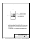
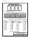
TableU.RemoteEPO
1(NC)
4 (COMMON)
TWISTED
WIRES
UPS TB1
REMOTE
EPO
SWITCH
REMOTE
EPO
SWITCH
2 (COMMON)
3(NO)
(NC TYPE)
(NO TYPE)
TWISTED
WIRES
OR
LATCHING-TYPE
SWITCH ONLY
INSTALLJUMPER
IFSWITCHNOT
INSTALLEDTHIS
POSITION
SWITCH ONLY
LATCHING-TYPE
Remote EPO switch rating i s 24 Vdc, 1A minimum.
NOTE: This switch must be a dedicated latching-type switch not
tied into any other circuits.