


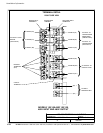
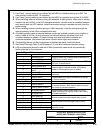
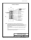
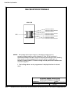
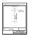
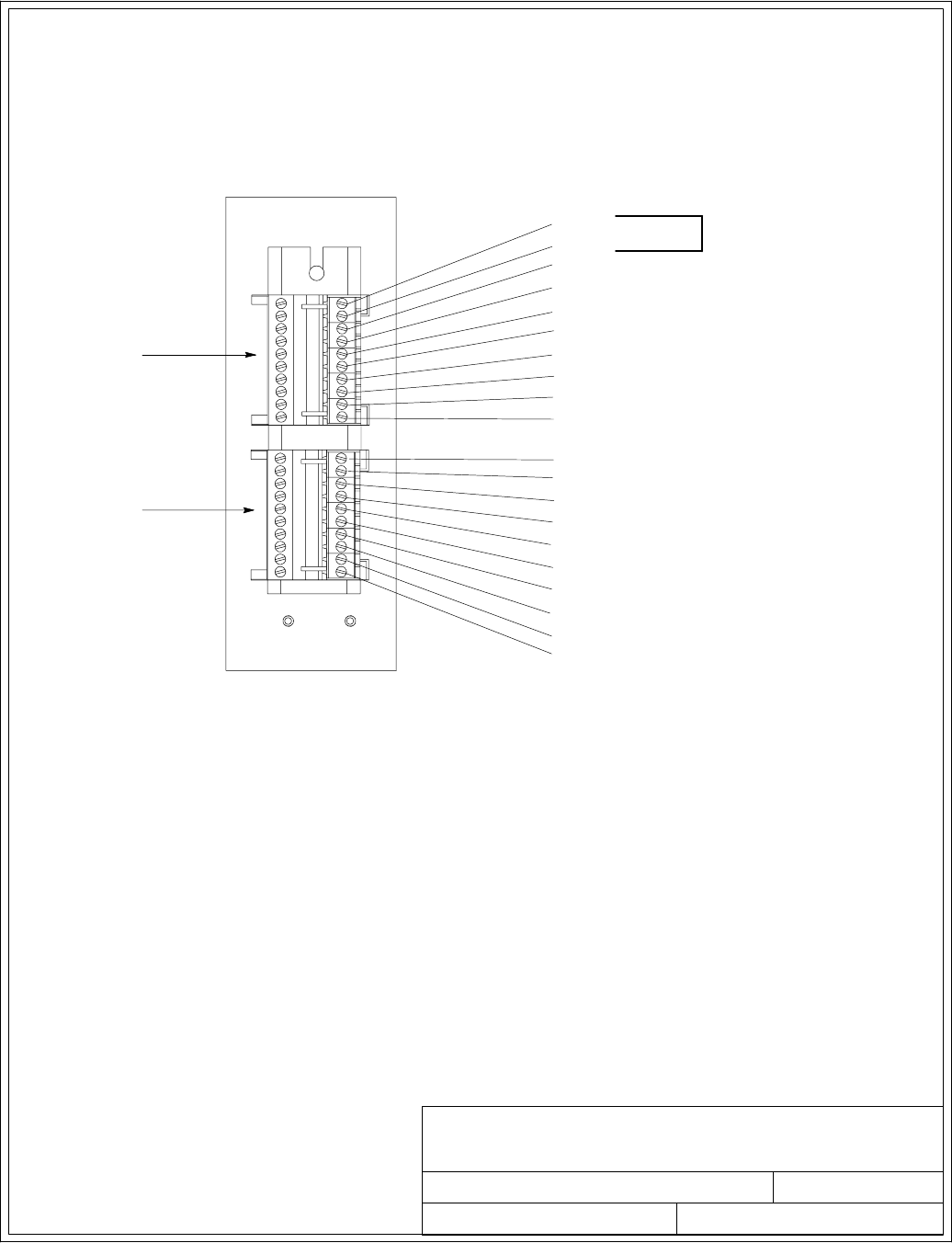
NOTE: 1. All building alarm inputs require an isolated normally-open or
normally-closed contact or switch (rated at 24 Vdc, 20 mA minimum)
connected between the alarm input and common terminal as shown. Building
alarm inputs can be programmed for use with either normally-open or
normally-closed contacts. All control wiring and relay and switch contacts are
customer-supplied.
2. The building alarms can be programmed to display the alarm functional
name.
3. A jumper wire must be connected between pins 1 and 2 on TB1, if the
normally-closed EPO contact is not used.
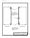
032406B
164201604---8
DESCRIPTION:
DATE:
DRAWING NO: SHEET:
REVISION:
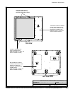
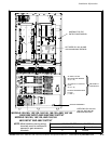
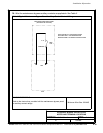
INTERFACE WIRING I NSTALLATION
NOTES AND TERMINAL LO CATIONS
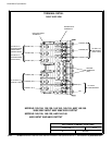
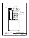
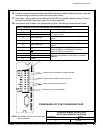
INTERFACE TERMINALS
3of13
BUILDING ALARM 2 RETURN
BUILDING ALARM 1
1
10
1
10
TB1
TB2
BUILDING ALARM 1 RETURN
BUILDING ALARM 2
ALARM RELAY NC
ALARM RELAY COMMON
ALARM RELAY NO
REMOTE EPO NO
REMOTE EPO NC
EPO COMMON
BATTERY BREAKER AUX
BATTERY BREAKER AUX RETURN
BATTERY UVR (+)
BATTERY UVR ( ---)
UPS
ON BYPASS NO
ON BYPASS RE TURN
ON INVERTER NC
ON INVERTER RETURN
EPO COMMON
ALARM RELAY COMMON
JUMPER REQUIRED
IF NOT USED
Installation Information
A-35
EATON Powerware
®
9390 UPS (100–160 kVA) Installation and Operation Manual S 164201604 Rev B powerware.com