


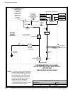
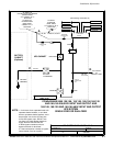
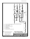
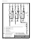
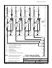
POWER WIRING INSTALLATION NOTES
032406B
164201604---5
3of15
DESCRIPTION:
DATE:
DRAWING NO: SHEET:
REVISION:
Installation Information
A-14
EATON Powerware
®
9390 UPS (100–160 kVA) Installation and Operation Manual S 164201604 Rev B powerware.com
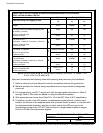
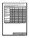
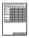
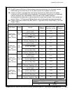
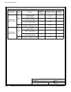
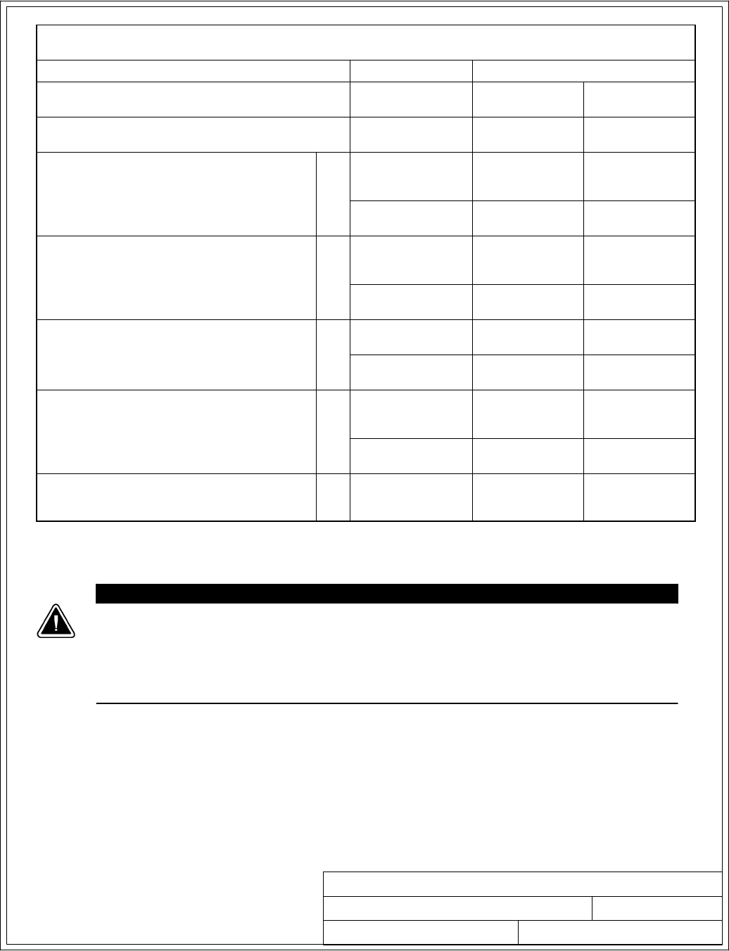
Table G. INPUT/OUTPUT Ratings & External Wiring Requirements for the Powerware
9390---160/160
Units Rating 50/60 Hz
BasicUnitRatingat0.9laggingpFload
kVA
kW
160
144
160
144
Input and Bypass Input
Output
VOLTS
VOLTS
208/220
208/220
480
480
AC Input to UPS Rectifier (0.98 min. pF)
Full Load Current plus Battery Recharge Current
(3) Phases , (1) Ground
A
Amps 480 210
Minimum Conduc tor Size
Number per Phase
AWG or kcmil
(each)
400
(2)
1/0
(2)
AC Input to UPS Bypass
Full Load Current
(3) Phases, (1) Neutral---if required, (1) Ground
B
Amps 444/420 192
Minimum Conduc tor Size
Number per Phase
AWG or kcmil
(each)
400
(2)
1/0
(2)
DC Input from Battery to UPS
(1) Positive, (1) Negative
C
Vdc
Amps@ (2.0V/cell)
384---480
403
432---480
403
Minimum Conduc tor Size
Number per Pole
AWG or kcmil
(each)
250
(2)
250
(2)
AC Output to Critical Load
Full Load Current
(3) Phases, (1) Neutral---if required, (1) Ground
D
Amps 444/420 192
Minimum Conduc tor Size
Number per Phase
AWG or kcmil
(each)
400
(2)
1/0
(2)
Neutral Bonding Jumper
Minimum Conduc tor Size
Number (S ee Note 7)
---
AWG or kcmil
(each)
1/0
(2)
2
(2)
NOTE: Callout letters A, B, C,andD map to Drawing 164201604---4, sheets 1 of 6,
2of6,4of6,5of6,and6of6.
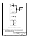
CAUTION
DELTA SOURCES (TN-S) - The Powerware 9390 UPS system can be operated only from a delta
supply source that is fully floating and if the neutral-forming transformer kit (PN 103005400) is
installed in the UPS. The UPS cannot be operated from a mid-point or end-point grounded
delta supply source. With this type of supply source, there is no capability to provide an output
neutral. In no circumstances shall a neutral to ground bonding jumper be installed in the UPS.
8. The UPS cabinet is shipped with a debris shield covering the ventilation grill on top of the
unit. Do not remove the d ebris shield until installation is complete. However, remove the
shield before operating the UPS. Once the debris shield i s removed, do not place objects
on the ventilation grill.
9. Refer to Section I of this manual for installation instructions.