


Using t he Control Panel
9-2
EATON Powerware
®
9390 UPS (100–160 kVA) Installation and Operation Manual S 164201604 Rev B powerware.com
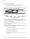
9.1 Using the LCD and Pushbuttons
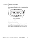
The LCD on the control panel provides an operator interface with the UPS system.
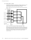
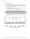
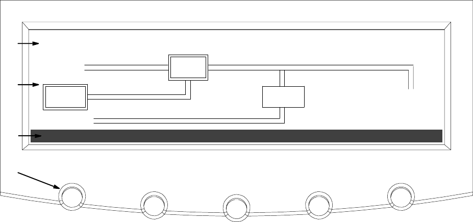
Figure 9-2 identifies the display areas discussed in the following sections.
METERSEVENTS SETUP
ALARM: INPUT AC UNDER VOLTAGE
OUTPUT
BATT
UPS
INPUT
STSW
A
B
C
D
CONTROLS LOAD OFF
BYP ASS
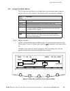
Figure 9-2. Parts of the LCD
A The UPS status area automatically scrolls between the Powerware model number, current date
and time, active alarms, active notices, and load percent and battery runtime for the UPS.
Shown is a typical alarm message. For more information about alarms and notices, see
Chapter 12, “Responding to System Events.”
B The information area contains data about UPS status and operations.
C The menu bar lists the titles of the available screens. To select a screen, press the pushbutton
underneath the desired screen.
D The navigation pushbuttons function depending on the screen displayed. Use the pushbuttons
to select menu screens or scroll through availablescreens.TheLCDoptionsabovethe
pushbuttons indicate each pushbutton’s function.
You can use the LCD and the pushbuttons to:
Ī Look at a log of UPS e vents (alarms, notices, and commands) (see paragraph 9.2.2)
Ī Monitor UPS operation (see paragraph 9.2.3)
Ī Set UPS parameters (see paragraphs 9.2.8 and 9.2.9)
Ī Control UPS operation (see paragraph 9.3)
After approximately 30 minutes, the display screen darkens. To restore the screen, press
any pushbutton once.