


Using Features and Options
11-5
EATON Powerware
®
9390 UPS (100–160 kVA) Installation and Operation Manual S 164201604 Rev B powerware.com
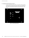
11.5 Supervisory Contact Module II
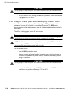
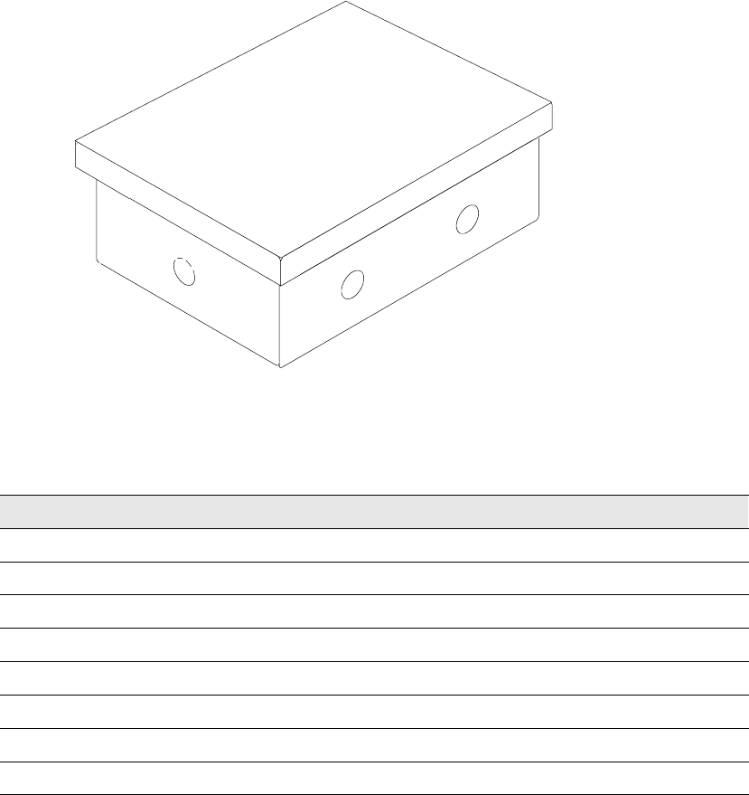
An optional SCM II establishes an interface between the UPS system and the customer’s
monitor. This interface allows the customer to monitor operational status of the UPS
system equipment. The SCM II can be flush-mounted or surface-mounted on a desktop, or
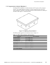
secured to a wall. Figure 11-3 shows the SCM II.
Figure 11-3. Supervisory Contact Module II
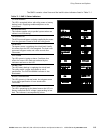
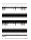
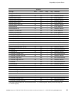
TheSCMIIprovidessignalsfortheindicationsshowninTable11-3.
Table 11-3. SCM II Status Indicators and Connections
Indication
TB-2 Connections
SYSTEM NORMAL
TB2-1 through TB2-3
NO REDUNDANCY
TB2-4 through TB2-6
ON GENERATOR
TB2-7 through TB2-9
BYPASS NOT AVAILABLE
TB2-10 through TB2-12
ON BATTERY
TB2-13 through TB2-15
UPS ALARM
TB2-16 through TB2-18
ON BYPASS
TB2-19 through TB2-21
SHUTDOWN IMMINENT
TB2-22 through TB2-24