


091505A
164201604---8
DESCRIPTION:
DATE:
DRAWING NO: SHEET:
REVISION:
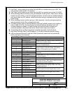
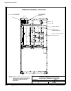
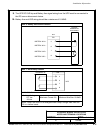
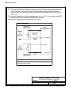
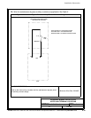
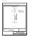
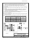
INTERFACE WIRING I NSTALLATION
NOTES AND TERMINAL LO CATIONS
POWERWARE HOT SYNC CAN BRIDGE CARD
CONNECTIONS FOR PARALLEL SYSTEM CONTROL
CONNECTIONS FOR RMP II, RIM II, OR SCM II
BUILDING ALARM 2 REPLACEMENT
J3
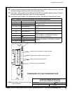
NOTE: All interface wiring is to be provided
by the customer.
CONNECTIONS FOR BYPASS STATUS
9of13
Installation Information
A-41
EATON Powerware
®
9390 UPS (100–160 kVA) Installation and Operation Manual S 164201604 Rev B powerware.com
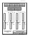
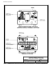
16. Conduit must be installed between the UPM cabinets for parallel i nterface wiring. Install the
interface wiring in separate conduit from the power wiring.
17. Use Class 1 wiring methods (as defined b y the N EC) for parallel interface wiring. The wire
should be shielded twisted pair, rated for 5 amps maximum.
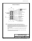
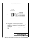
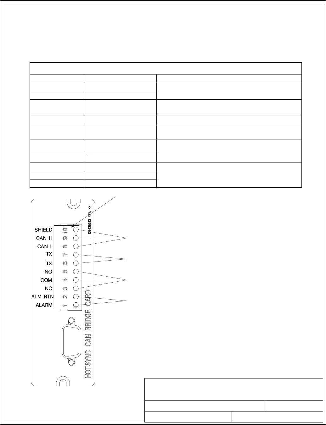
18. See Table X and Chapter 6 for Powerware Hot Sync CAN Bridge Card interface wiring.
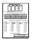
Table X. Powerware Hot Sync CAN Bridge Card Interface Connections
Terminal J3 Name Description
1 Alarm
Programmable UPS alarm. Activated by a remote
dry contact closure.
2 Alarm Rtn
3 Alarm Relay NC
Normally-closed contact opens when UPS is on
bypass.
4 Alarm Relay Com Bypass contact return.
5 Alarm Relay NO
Normally-open contact closes when UPS is on
bypass.
6
TX
Remote Monitor Panel II (RMP II), Relay Interface
Module II (RIM II), and Supervisory Contact
Module II (SCM II) connections.
7
TX
8 CAN L
Computer Area Network (CAN) Input for parallel
operation.
9 CAN H
10 Shield