


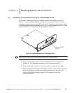


Installing Options and Accessories
6-5
EATON Powerware
®
9390 UPS (100–160 kVA) Installation and Operation Manual S 164201604 Rev B powerware.com
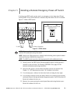
NOTE When installing signal wiring for CAN card J3 terminals, conduit must be
installed between the device and the UPS cabinet.
NOTE Remove the UPS cabinet top or bottom conduit landing plate to drill or punch
conduit holes (see Drawing 164201604-6 on page A -27).
4. Remove the X-Slot conduit landing plate from the UPS cabinet to drill or punch
conduit holes (see Drawing 164201604-6 on page A-27).
5. Reinstall the conduit landing plate.
6. Install conduit between the UPS and RIM II. See Appendix A for UPS cabinet and
RIM II wiring access information.
7. Install wiring between the UPS and RIM II. See Drawing 164201604-8 starting on
page A-33 for Powerware Hot Sync CAN Bridge Card and RIM II location, terminal
location, and wiring information.
NOTE
120 Vac for the RIM II should be supplied from the critical bus by facility
planners or the customer.
8. Install 120 Vac power wiring from the critical bus to the RIM II. See Drawing
164201604-8 starting on page A-33 for terminal location and wiring information.
NOTE
Setup of the Powerware Hot Sync CAN Bridge Card must be performed by an
authorized Eaton Customer Service Engineer. Contact service to schedule a date.
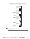
9. Contact your Eaton service representative for verification and testing of the RIM II
and its connections prior to making connections with J1 through J4 (see Table 6-1
and Drawing 164201604-12 on page A-52).
You can order interface cables separately for connecting to the 15-Pin D-Sub
Connectors.
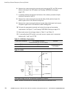
Table 6-1. J1 through J4 Interface Connectors
Status J1 through J4 Description
UPS AVAILABLE
Pins 1 and 12 Contacts are closed when the UPS is offline.
UPS OFFLINE
Pins 3 and 13 Contacts are closed when the UPS is operating in
Normal mode.
BATTERY WEAK
Pins 5 and 14 Contacts are closed when approximately two minutes of
battery time is remaining before the critical load is lost.
UTILITY FAILURE
Pins 6 and 15 Contacts are closed when Utility Failure is detected.