


Understanding UPS Operation
7-4
EATON Powerware
®
9390 UPS (100–160 kVA) Installation and Operation Manual S 164201604 Rev B powerware.com
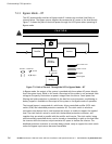
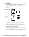
7.2.2 Normal Mode – RT
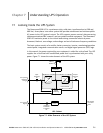
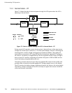
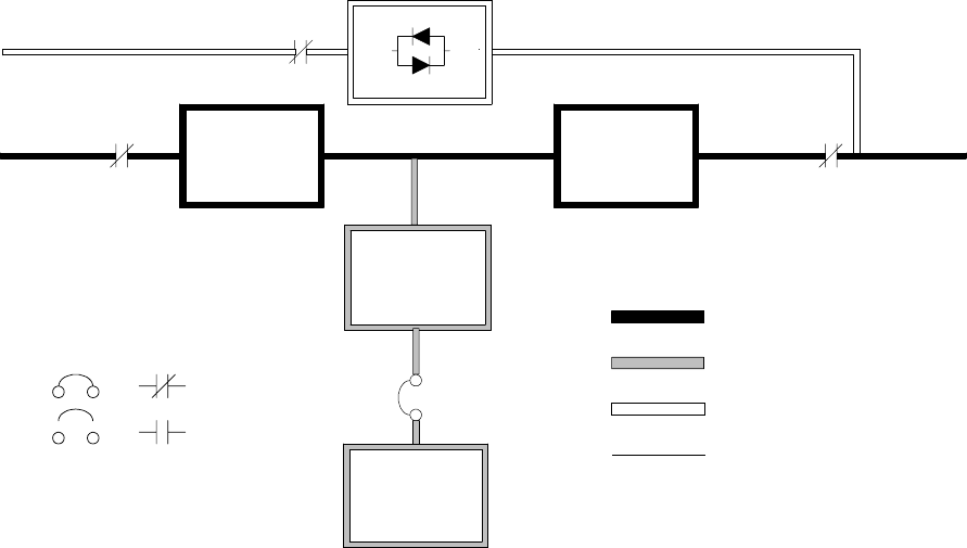
Figure 7-2 shows the path of electrical power through the UPS system when the UPS is
operating in Normal mode.
Static
Switch
K5
Rectifier Inverter
K1 K3
Battery
Converter
Battery
Battery
Breaker
Main Power Flow
Trickle Current
Energized
De-Energized
Closed
Open
Breakers Contactors
Static
Switch
K5
Rectifier Inverter
K1 K3
Battery
Converter
Battery
Battery
Breaker
Main Power Flow
Trickle Current
Energized
De-Energized
Closed
Open
Breakers Contactors
Figure 7-2. Path of Current Through the UPS in Normal Mode – RT
During normal UPS operation, power for the system is derived from a utility input source
through the rectifier input contactor K1. The front panel displays “Normal,” indicating the
incoming power is within voltage and frequency acceptance windows. Three-phase AC
input power is converted to DC using IGBT devices to produce a regulated DC voltage to
the inverter. The battery is charged directly from the regulated rectifier output through a
buck or boost DC converter, depending on whether the system is 208V or 480V and the
size of the b attery string attached to the unit.
The battery converter derives its input from the regulated DC output of the rectifier and
provides either a boosted or bucked regulated DC voltage charge current to the battery.
The UPS monitors the battery charge condition and reports the status on the control panel.
The battery is always connected to the UPS and ready to support the inverter should the
utility input become unavailable.