


1of15
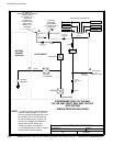
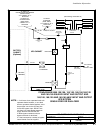
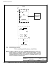
POWER WIRING INSTALLATION NOTES
032406B
164201604---5
DESCRIPTION:
DATE:
DRAWING NO: SHEET:
REVISION:
Installation Information
A-12
EATON Powerware
®
9390 UPS (100–160 kVA) Installation and Operation Manual S 164201604 Rev B powerware.com
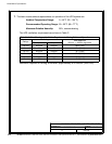
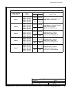
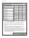
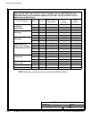
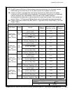
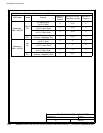
Table E. INPUT/OUTPUT Ratings & External Wiring Requirements for the Powerware
9390---120/100 and 9390---160/100
Units Rating 50/60 Hz
BasicUnitRatingat0.9laggingpFload
kVA
kW
100
90
100
90
Input and Bypass Input
Output
VOLTS
VOLTS
208/220
208/220
480
480
AC Input to UPS Rectifier (0.98 min. pF)
Full Load Current plus Battery Recharge Current
(3) Phases , (1) Ground
A
Amps 300 130
Minimum Conduc tor Size
Number per Phase
AWG or kcmil
(each)
3/0
(2)
4/0
(1)
AC Input to UPS Bypass
Full Load Current
(3) Phases, (1) Neutral---if required, (1) Ground
B
Amps 278/262 120
Minimum Conduc tor Size
Number per Phase
AWG or kcmil
(each)
3/0
(2)
4/0
(1)
DC Input from Battery to UPS
(1) Positive, (1) Negative
C
Vdc
Amps@ (2.0V/cell)
384---480
252
432---480
252
Minimum Conduc tor Size
Number per Pole
AWG or kcmil
(each)
2/0
(2)
2/0
(2)
AC Output to Critical Load
Full Load Current
(3) Phases, (1) Neutral---if required, (1) Ground
D
Amps 278/262 120
Minimum Conduc tor Size
Number per Phase
AWG or kcmil
(each)
3/0
(2)
4/0
(1)
Neutral Bonding Jumper
Minimum Conduc tor Size
Number (S ee Note 7)
---
AWG or kcmil
(each)
1/0
(1)
2
(1)
NOTE: Callout letters A, B, C,andD map to Drawing 164201604---4, sheets 1 of 6,
2of6,4of6,5of6,and6of6.
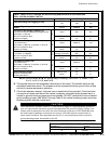
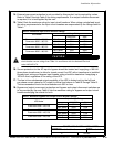
Read and understand the following notes while planning and performing the ins tallation:
1. Refer to national and local electrical codes for acceptable external wiring practices.
2. Material and labor for external wiring requirements are to be provided by designated
personnel.
3. For external wiring, use 90° C copper wire. See the appropriate information in Table E
through Table G. Wire sizes are based on using the specified breakers.
4. Wire ampacities are chosen from Table 310---16 of the NEC. Wire is 90°C specification.
5. If installing, as part o f the UPS system, a maintenance bypass without a rectifier input
breaker, a minimum of two separate feeds with upstream feeder breakers, or one feed with
two upstream feeder breakers, must be provided: one for the UPS and one for the
maintenance bypass input. DO NOT use one feed or a single-feeder breaker to supply
both the UPS and the maintenance bypass.