


091505A
164201604---8
DESCRIPTION:
DATE:
DRAWING NO: SHEET:
REVISION:
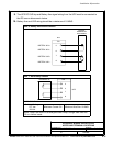
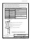
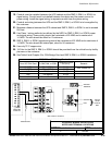
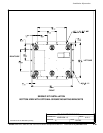
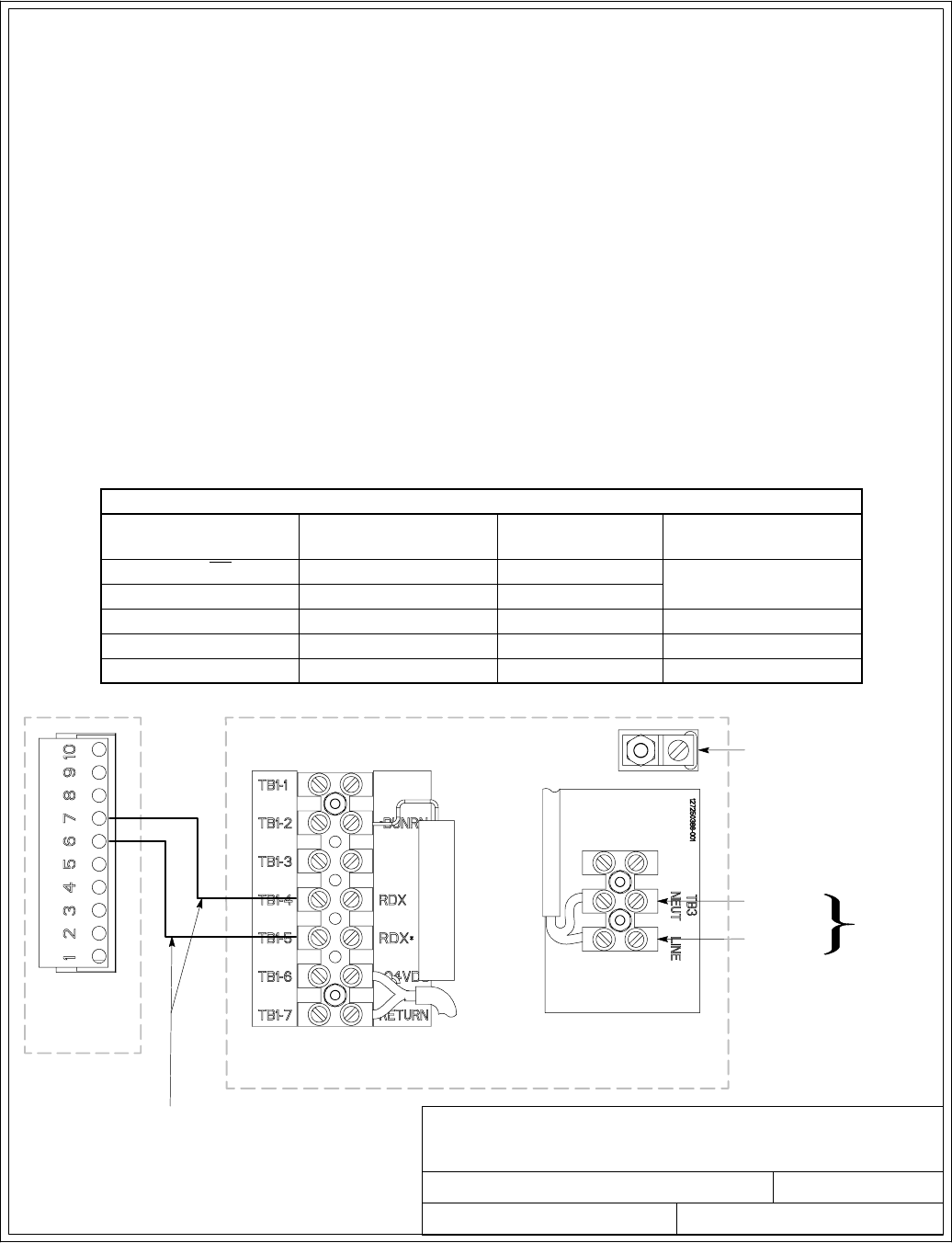
INTERFACE WIRING I NSTALLATION
NOTES AND TERMINAL LO CATIONS
UPS CAN
CARD J3
120 VAC
FROM
CRITICAL
BUS
LINE
NEUTRAL
TWISTED PAIR
GROUND
TERMINAL
RMP II, RIM II, OR SCM II
13 of 13
Installation Information
A-45
EATON Powerware
®
9390 UPS (100–160 kVA) Installation and Operation Manual S 164201604 Rev B powerware.com
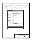
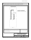
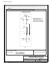
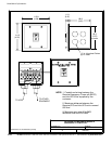
19. Conduit must be installed between the U PS cabinet and the RMP II, RIM II, or SCM II for
signal wiring. Conduit must be installed between the device and the power so urce for
power wiring. Install the signal wiring in separate conduit from the p ower wiring.
20. Conduit and wiri ng between the UPS and the RMP II, RIM II, or SCM II is to be supplied by
the customer.
21. Maximum distance between the UPS cabinet and RMP II, RIM II, or SCM II is not to exceed
500 feet.
22. Use Class 1 wiring methods (as defined by the N EC) for RMP II, RIM II, or SCM II power
and signal wiring. P o wer wiring should be a minimum of 22 AWG and a maximum of
14AWG.Thewireshouldberatedfor1Aminimum.
23. RMP II, RIM I I, or SCM II signal wiring should b e a minimum of 22 AWG and a maximum of
14AWG.Thewireshouldbetwistedpair,ratedfor5Amaximum.
24. Use only 75°C copper wire.
25. 120 Vac for t he RMP II, RIM II, or SCM II should be provided from the critical bus by facility
planners or the customer.
26. See Table X and Chapter 6 for CAN Bridge Card and RMP II, RIM II, or SCM II installation.
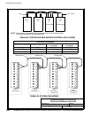
RMP, RIM, or SCM Wiring Terminations
From UPS CAN Card To RMP, RIM, or SCM
Tightening Torque
Nm (lb in)
Remarks
J3–6 (TX) TB1–5 (RDX
*
) 0.9 (8)
Use Twisted Pair
J3–7 (TX) TB1–4 (RDX) 0.9 (8)
N/A TB3 Line 0.9 (8)
N/A TB3 Neutral 0.9 (8)
N/A Ground Te rminal 2.7 (24) Maximum