


Installing Options and Accessories
6-3
EATON Powerware
®
9390 UPS (100–160 kVA) Installation and Operation Manual S 164201604 Rev B powerware.com
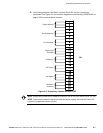
11. Install parallel system backup control (pull chain) wiring between UPMs. See
Drawing 164201604-8 starting on page A-33 for terminal locations and wiring
information.
12. Install parallel system backup control (pull chain) wiring between the bypass relay
and building alarm 2. See Drawing 164201604-8 starting on page A-33 for terminal
locations and wiring information.
NOTE
Setup of the Powerware Hot Sync CAN Bridge Card for parallel operation must
be performed by an a uthorized Eaton Customer Service Engineer. Contact service to
schedule a date.
13. When all wiring is complete, reinstall the safety shield panels removed in previous
steps. Secure with the retained hardware.
14. Close the control panel door and secure with the retained hardware.
15. Reinstall the doors removed previously and secure with the retained hardware.
16. Close the doors and secure the latch.
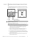
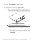
6.3 Installing a Remote Monitor Panel II
To install RMP II wiring, perform the following procedure:
1. Verify the UPS system is turned off and all power sources are removed. See
Chapter 10, “UPS Operating Instructions,” for shutdown instructions.
2. Perform the procedure listed in paragraph 6.1.
NOTE
If mounting to a hollow wall, secure the enclosure to a wood or metal stud within
the wall. Do not use hollow wall anchors.
3. Securely mount the RMP II at the desired location. See drawing 164201604-11 on
page A-51 for mounting hole locations.
NOTE
When installing signal wiring for CAN card J3 terminals, conduit must be
installed between the device and the UPS cabinet.
NOTE Remove the UPS cabinet top or bottom conduit landing plate to drill or punch
conduit holes (see Drawing 164201604-6 on page A -27).
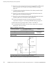
4. Remove the X-Slot conduit landing plate from the UPS cabinet to drill or punch
conduit holes (see Drawing 164201604-6 on page A-27).
5. Reinstall the conduit landing plate.
6. Install conduit between the UPS and RMP II. See Appendix A for U PS cabinet and
RMP II wiring access information.