


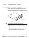


Installing Options and Accessories
6-4
EATON Powerware
®
9390 UPS (100–160 kVA) Installation and Operation Manual S 164201604 Rev B powerware.com
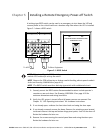
7. Install wiring between the UPS and RMP II. See Drawing 164201604-8 starting on
page A-33 for Powerware Hot Sync CAN Bridge Card and RMP II location, terminal
location, and wiring information.
NOTE
120 Vac for the RMP II should be supplied from the critical bus by facility
planners or the customer.
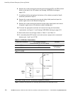
8. Install 120 Vac power wiring from the critical bus to the RMP II. See Drawing
164201604-8 starting on page A-33 for terminal location and wiring information.
NOTE
Setup of the Powerware Hot Sync CAN Bridge Card must be performed by an
authorized Eaton Customer Service Engineer. Contact service to schedule a date.
9. To check the operation of the RMP II, ensure that the UPS is supplying the load v ia
inverter or bypass. If the indicators on the RMP II show the appropriate status,
then it is operating correctly.
If the communication link between the UPS and the RMP II is n ot present, the
RMP II performs a self-test (all indicators flash and the horn beeps at one-second
intervals). If the self-test occurs, check all h arness connectors and the fuse for
proper seating. If all connections are secure but the RMP II continues to self-test,
replace the fuse with the spare included in the hardware kit. If a fuse replacement
does not correct the problem, contact your Eaton service representative for
verification that the RMP II is working correctly.
10. To test the indicator lamps, press and hold the horn silence pushbutton for
3 seconds. All lamps should illuminate, and the horn sounds continuously until you
release the pushbutton.
6.4 Installing a Relay Interface Module II
To install RIM II wiring, perform the following procedure:
1. Verify the UPS system is turned off and all power sources are removed. See
Chapter 10, “UPS Operating Instructions,” for shutdown instructions.
2. Perform the procedure listed in paragraph 6.1.
NOTE
If mounting to a hollow wall, secure the enclosure to a wood or metal stud within
the wall. Do not use hollow wall anchors.
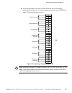
3. Securely mount the RIM II at the desired location. See drawing 164201604-12 for
mounting hole locations.