


1of13
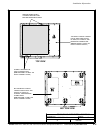
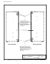
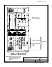
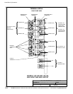
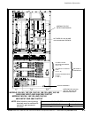
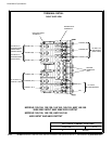
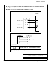
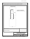
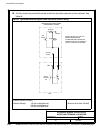
INTERFACE WIRING I NSTALLATION
NOTES AND TERMINAL LO CATIONS
032406B
DESCRIPTION:
DATE:
DRAWING NO: SHEET:
REVISION:
164201604---8
Installation Information
A-33
EATON Powerware
®
9390 UPS (100–160 kVA) Installation and Operation Manual S 164201604 Rev B powerware.com
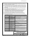
1. Use Class 1 wiring methods (as defined by the NEC) for interface wiring up to 30V. The
wire should be rated at 24V, 1A minimum.
2. Use Class 2 wiring methods (as defined by the NEC) for interface wiring from 30 to 600V.
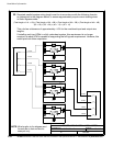
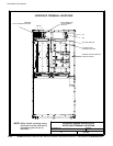
3. When installing external interface wiring (for example, building alarm, relay output, battery
breaker trip, and X-Slot) to the UPS interface terminals, conduit must be installed between
each device and the UPS cabinet. Install the interface wiring in separate conduit from the
power wiring.
4. When installing internal interface wiring to X-Slot terminals, route the wiring through the
internal opening in the X-Slot communication bay.
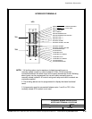
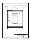
5. All building alarm inputs or remote features require an isolated normally-open contact or
switch (rated at 24 Vdc, 20 mA minimum) connected between the alarm input and
common terminal as shown. All control wiring and relay and switch contacts are
customer-supplied. Use twisted-pair wires for each alarm input and common.
6. The building alarms can be programmed to d isplay the alarm functional name.
7. See Table R through Table X and Chapters 3, 5, and 6 for customer interface wiring.
8. LAN and telephone drops for use with X-Slot connectivity cards must be provided by
facility planners or the customer.
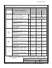
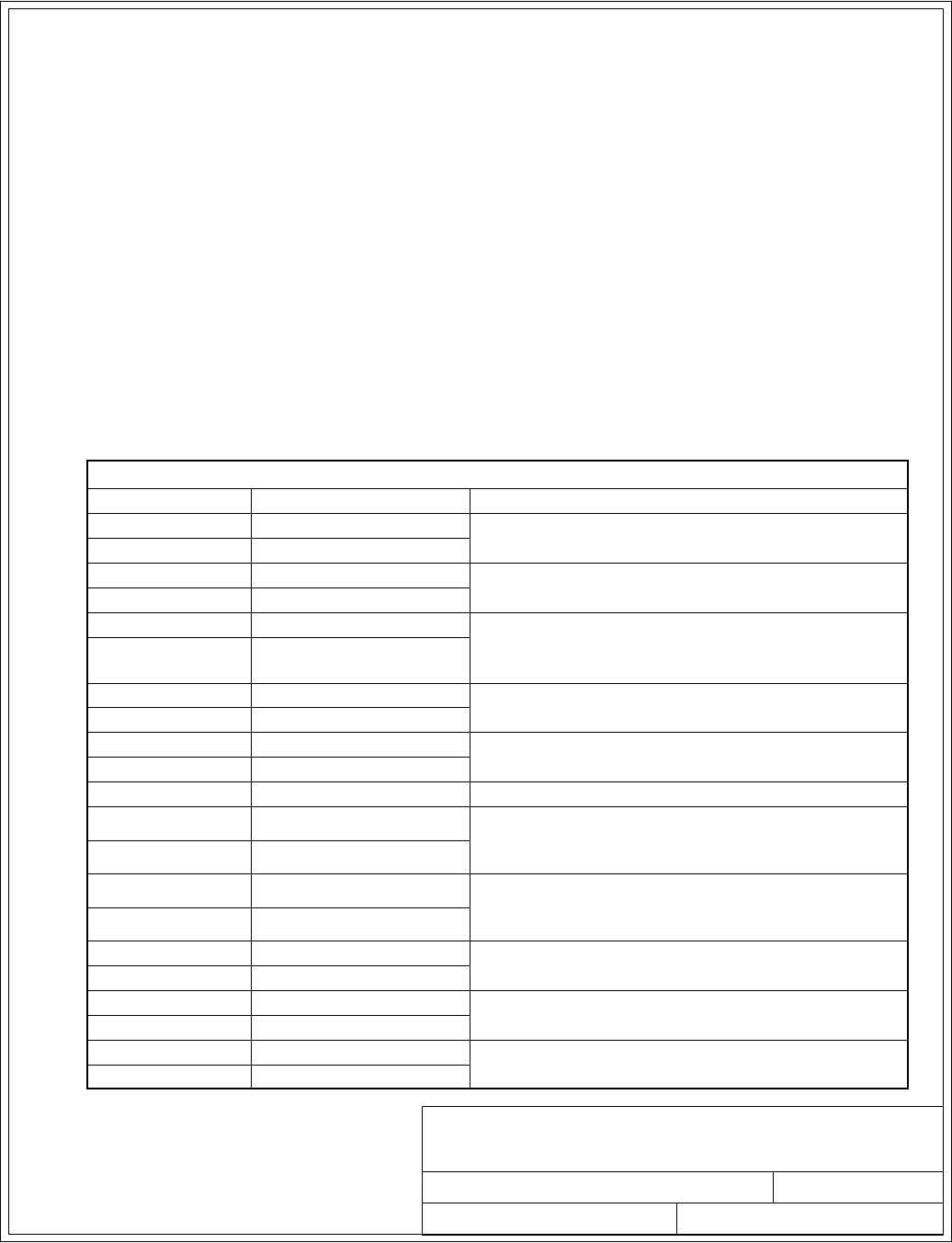
Table R. TB1 and TB2 Interface Connections
Terminal TB1 Name Description
1 Remote EPO NC
Normally-closed dry contacts used to activate EPO
of UPS from a remote switch
2 Remote EPO Common
3 Remote EPO NO
Normally-open dry contacts used to activate EPO of
UPS from a remote switch
4 Remote EPO Common
5 Battery Breaker Aux
Contacts used to indicate whether UPS battery
breaker or disconnect is open or closed.
6
Battery Breaker Aux
Return
7 Battery UVR (+)
Contacts used to open battery breaker or
disconnect.
8 Battery UVR (---)
9 Building Alarm 1
Programmable UPS alarm. Ac tivated by a remote
dry contact closure.
10 Building Alarm 1 Return
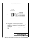
Terminal TB2 Name Description
1 Building Alarm 2
Programmable UPS alarm. Ac tivated by a remote
dry contact closure. Also used for backup control
(pull chain) for parallel operation.
2 Building Alarm 2 Return
3 On Bypass Return
Normally-open contact closes when UPS is on
bypass. Also used for backup control (pull chain)
for parallel operation.
4 On Bypass NO
5 Alarm Relay NC
General purpose normally-closed relay contact.
6 Alarm Relay Common
7 Alarm Relay NO
General purpose normally-open relay contact.
8 Alarm Relay Common
9 On Invert er NC
Normally-closed contact opens when output
contactor closes.
10 On Inverter Return