


Installing Options and Accessories
6-2
EATON Powerware
®
9390 UPS (100–160 kVA) Installation and Operation Manual S 164201604 Rev B powerware.com
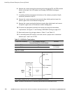
4. Install wiring from the Powerware Hot Sync CAN Bridge Card in accordance with
the instructions listed below:
Ī Parallel system wiring (see paragraph 6.2)
Ī RMP II wiring (see paragraph 6.3)
Ī RIM II (see paragraph 6.4)
Ī SCM II (see paragraph 6.5)
6.2 Installing Parallel System Control Wiring
NOTE When installing external wiring to the X-Slot CAN card, conduit must be
installed to the UPS cabinet. When installing internal wiring to the X-Slot CAN card
terminals, route the wiring through the internal opening in the X-Slot communication
bay.
NOTE When installing interface wiring for the parallel system pull chain, conduit
must be installed between UPMs.
To install parallel system control wiring, perform the following procedure:
1. Verify the UPS system is turned off and all power sources are removed. See
Chapter 10, “UPS Operating Instructions,” for shutdown instructions.
2. Perform the procedure listed in paragraph 6.1.
3. If not already removed, remove the doors. Remove the retaining screws located
inside each door at the top and bottom hinge pivot points, then lift the door off.
Retain the hardware for later u se.
4. Remove the screws securing the control panel door and swing the door open.
Retain the hardware for later u se.
5. Remove the screws securing the top internal safety shield panel. Remove the panel
to gain access to the TB1 and TB2 terminal blocks, X-Slot communication bays,
and the top conduit landing plate (see Drawing 164201604-8 starting on
page A-33). Retain the hardware for later use.
6. If installing interface wiring from the bottom of the cabinet, proceed to Step 7;
otherwise, proceed to Step 8.
7. Remove the screws securing the bottom internal safety shield panel and remove
the panel to gain access to the bottom conduit landing plate.
8. Remove the X-Slot conduit landing plate from the UPS cabinet to drill or punch
conduit holes (see Drawing 164201604-6 on page A-27).
9. Reinstall the conduit landing plate and install the conduit.
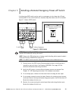
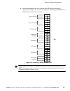
10. Install CAN wiring between UPMs. See Drawing 164201604-8 starting on page A-33
for Powerware Hot Sync CAN Bridge Card location, terminal location, and wiring
information.